Speed Matters: How Ethernet Went From 3 Mbps to 100 Gbps… and Beyond

Archive for September, 2011

Iteration

  • The action or a process of iterating or repeating: as
    • A procedure in which repetition of a sequence of operations yields results successively closer to a desired result
    • The repetition of a sequence of computer instructions a specified number of times or until a condition is met — compare recursion
  • One execution of a sequence of operations or instructions in an iteration

Iteration means the act of repeating a process usually with the aim of approaching a desired goal or target or result. Each repetition of the process is also called an “iteration,” and the results of one iteration are used as the starting point for the next iteration.

Mathematics

Iteration in mathematics may refer to the process of iterating a function i.e. applying a function repeatedly, using the output from one iteration as the input to the next. Iteration of apparently simple functions can produce complex behaviors and difficult problems – for examples, see the Collatz conjecture and juggler sequences.

Another use of iteration in mathematics is in iterative methods which are used to produce approximate numerical solutions to certain mathematical problems. Newton’s method is an example of an iterative method.

Computing

Iteration in computing is the repetition of a process within a computer program. It can be used both as a general term, synonymous with repetition, and to describe a specific form of repetition with a mutable state.

When used in the first sense, recursion is an example of iteration, but typically using a recursive notation, which is typically not the case for iteration.

However, when used in the second (more restricted) sense, iteration describes the style of programming used in imperative programming languages. This contrasts with recursion, which has a more declarative approach.

Here is an example of iteration relying on destructive assignment, in imperative pseudo code:

  • var i, a = 0        // initialize a before iteration
  • for i from 1 to 3    // loop three times
  • {
  • a = a + i       // increment a by the current value of i
  • }
  • print a              // the number 6 is printed

In this program fragment, the value of the variable i changes over time, taking the values 1, 2 and 3. This changing value—or mutable state—is characteristic of iteration.

Iteration can be approximated using recursive techniques in functional programming languages. The following example is in Scheme. Note that the following is recursive (a special case of iteration) because the definition of “how to iterate”, the iter function, calls itself in order to solve the problem instance. Specifically it uses tail recursion, which is properly supported in languages like Scheme so it does not use large amounts of stack space.

  • ;; sum : number -> number
  • ;; to sum the first n natural numbers
  • (define (sum n)
  • (if (and (integer? n) (> n 0))
  • (let iter ([n n] [i 1])
  • (if (= n 1)
  • i
  • (iter (- n 1) (+ n i))))
  • ((assertion-violation
  • ‘sum “invalid argument” n))))

An iterator is an object that wraps iteration.

Iteration is also performed using a worksheet, or by using solver or goal seek functions available in Excel. Many implicit equations like the Colebrook equation can be solved in the convenience of a worksheet by designing suitable calculation algorithms.

Many of the engineering problems like solving Colebrook equations reaches 8-digit accuracy in as small as 12 iterations and a maximum of 100 iterations is sufficient to reach a 15-digit accurate result.

Project Management

Iterations in a project context may refer to the technique of developing and delivering incremental components of business functionality, product development or process design. This is most often associated with agile software development, but could potentially be any material. A single iteration results in one or more bite-sized but complete packages of project work that can perform some tangible business function. Multiple iterations recurse to create a fully integrated product. This is often compared with the waterfall model approach.

Bit Error Rate

In digital transmission, the number of bit errors is the number of received bits of a data stream over a communication channel that have been altered due to noise, interference, distortion or bit synchronization errors.

The bit error rate or bit error ratio (BER) is the number of bit errors divided by the total number of transferred bits during a studied time interval. BER is a unitless performance measure, often expressed as a percentage.

The bit error probability pe is the expectation value of the BER. The BER can be considered as an approximate estimate of the bit error probability. This estimate is accurate for a long time interval and a high number of bit errors

In telecommunication transmission, the bit error rate (BER) is the percentage of bits that have errors relative to the total number of bits received in a transmission, usually expressed as ten to a negative power. For example, a transmission might have a BER of 10 to the minus 6, meaning that, out of 1,000,000 bits transmitted, one bit was in error. The BER is an indication of how often a packet or other data unit has to be retransmitted because of an error. Too high a BER may indicate that a slower data rate would actually improve overall transmission time for a given amount of transmitted data since the BER might be reduced, lowering the number of packets that had to be resent.

Example

As an example, assume this transmitted bit sequence:

0 1 1 0 0 0 1 0 1 1,

and the following received bit sequence:

0 0 1 0 1 0 1 0 0 1,

The number of bit errors (the underlined bits) is in this case 3. The BER is 3 incorrect bits divided by 10 transferred bits, resulting in a BER of 0.3 or 30%.

Packet Error Rate

The packet error rate (PER) is the number of incorrectly received data packets divided by the total number of received packets. A packet is declared incorrect if at least one bit is erroneous. The expectation value of the PER is denoted packet error probability pp, which for a data packet length of N bits can be expressed as

pp = 1 − (1 − pe)N,

assuming that the bit errors are independent of each other.

Similar measurements can be carried out for the transmission of frames, blocks, or symbols.

Factors Affecting the BER

In a communication system, the receiver side BER may be affected by transmission channel noise, interference, distortion, bit synchronization problems, attenuation, wireless multipath fading, etc.

The BER may be improved by choosing a strong signal strength (unless this causes cross-talk and more bit errors), by choosing a slow and robust modulation scheme or line coding scheme, and by applying channel coding schemes such as redundant forward error correction codes.

The transmission BER is the number of detected bits that are incorrect before error correction, divided by the total number of transferred bits (including redundant error codes). The information BER, approximately equal to the decoding error probability, is the number of decoded bits that remain incorrect after the error correction, divided by the total number of decoded bits (the useful information). Normally the transmission BER is larger than the information BER. The information BER is affected by the strength of the forward error correction code.

Analysis of the BER

The BER may be analyzed using stochastic computer simulations. If a simple transmission channel model and data source model is assumed, the BER may also be calculated analytically. An example of such a data source model is the Bernoulli source.

Examples of such simple channel models are:

  • Binary symmetric channel (used in analysis of decoding error probability in case of non-bursty bit errors on the transmission channel)
  • Additive white gaussian noise (AWGN) channel without fading.

A worst case scenario is a completely random channel, where noise totally dominates over the useful signal. This results in a transmission BER of 50%.

BER comparison between BPSK and differentially-encoded BPSK with gray-coding operating in white noise.

In a noisy channel, the BER is often expressed as a function of the normalized carrier-to-noise ratio measure denoted Eb/N0, (energy per bit to noise power spectral density ratio), or Es/N0 (energy per modulation symbol to noise spectral density).

For example, in the case of QPSK modulation and AWGN channel, the BER as function of the Eb/N0 is given by: BER = 1 / 2erfc(Eb / N0 / sqrt(2)).

People usually plot the BER curves to describe the functionality of a digital communication system. In optical communication, BER(dB) vs. Received Power(dBm) is usually used; while in wireless communication, BER(dB) vs. SNR(dB) is used.

Measuring the bit error ratio helps people choose the appropriate forward error correction codes. Since most such codes correct only bit-flips, but not bit-insertions or bit-deletions, the Hamming distance metric is the appropriate way to measure the number of bit errors. Many FEC coders also continuously measure the current BER.

A more general way of measuring the number of bit errors is the Levenshtein distance. The Levenshtein distance measurement is more appropriate for measuring raw channel performance before frame synchronization, and when using error correction codes designed to correct bit-insertions and bit-deletions, such as Marker Codes and Watermark Codes.

Bit Error Rate Test

BERT or bit error rate test is a testing method for digital communication circuits that uses predetermined stress patterns consisting of a sequence of logical ones and zeros generated by a pseudorandom binary sequencer.

A BERT typically consists of a test pattern generator and a receiver that can be set to the same pattern. They can be used in pairs, with one at either end of a transmission link, or singularly at one end with a loopback at the remote end. BERTs are typically stand-alone specialized instruments, but can be Personal Computer based. In use, the number of errors, if any, are counted and presented as a ratio such as 1 in 1,000,000, or 1 in 1e06.

Common types of BERT stress patterns

  • PRBS (Pseudo Random binary sequence) – A pseudorandom binary sequencer of N Bits. These pattern sequences are used to measure jitter and eye mask of TX-Data in electrical and optical data links.
  • QRSS (Quasi Random Signal Source) – A pseudorandom binary sequencer which generates every combination of a 20-bit word, repeats every 1,048,575 bits, and suppresses consecutive zeros to no more than 14. It contains high-density sequences, low-density sequences, and sequences that change from low to high and vice versa. This pattern is also the standard pattern used to measure jitter.
  • 3 in 24 – Pattern contains the longest string of consecutive zeros (15) with the lowest ones density (12.5%). This pattern simultaneously stresses minimum ones density and the maximum number of consecutive zeros. The D4 frame format of 3 in 24 may cause a D4 Yellow Alarm for frame circuits depending on the alignment of one bits to a frame.
  • 1:7 – Also referred to as “1 in 8”. It has only a single one in an 8-bit repeating sequence. This pattern stresses the minimum ones density of 12.5% and should be used when testing facilities set for B8ZS coding as the 3 in 24 pattern increases to 29.5% when converted to B8ZS.
  • Min/Max – Pattern rapid sequence changes from low density to high density. Most useful when stressing the repeater’s ALBO feature.
  • All Ones (or Mark) – A pattern composed of ones only. This pattern causes the repeater to consume the maximum amount of power. If DC to the repeater is regulated properly, the repeater will have no trouble transmitting the long ones sequence. This pattern should be used when measuring span power regulation. An unframed all ones pattern is used to indicate an AIS (also known as a Blue Alarm).
  • All Zeros – A pattern composed of zeros only. It is effective in finding equipment misoptioned for AMI, such as fiber/radio multiplex low-speed inputs.
  • Alternating 0s and 1s – A pattern composed of alternating ones and zeroes.
  • 2 in 8 – Pattern contains a maximum of four consecutive zeros. It will not invoke a B8ZS sequence because eight consecutive zeros are required to cause a B8ZS substitution. The pattern is effective in finding equipment misoptioned for B8ZS.
  • Bridgetap – Bridge taps within a span can be detected by employing a number of test patterns with a variety of ones and zeros densities. This test generates 21 test patterns and runs for 15 minutes. If a signal error occurs, the span may have one or more bridge taps. This pattern is only effective for T1 spans that transmit the signal raw. Modulation used in HDSL spans negates the Bridgetap patterns’ ability to uncover bridge taps.
  • Multipat – This test generates 5 commonly used test patterns to allow DS1 span testing without having to select each test pattern individually. Patterns are: All Ones, 1:7, 2 in 8, 3 in 24, and QRSS.
  • T1-DALY and 55 OCTET – Each of these patterns contain fifty-five (55), eight bit octets of data in a sequence that changes rapidly between low and high density. These patterns are used primarily to stress the ALBO and equalizer circuitry but they will also stress timing recovery. 55 OCTET has fifteen (15) consecutive zeroes and can only be used unframed without violating ones density requirements. For framed signals, the T1-DALY pattern should be used. Both patterns will force a B8ZS code in circuits optioned for B8ZS.

Bit Error Rate Tester

A bit error rate tester (BERT), also known as a bit error ratio testeror bit error rate test solution (BERTs) is electronic test equipment used to test the quality of signal transmission of single components or complete systems.

The main building blocks of a BERT are:

  • Pattern Generator, which transmits a defined test pattern to the DUT or test system
  • Error detector connected to the DUT or test system, to count the errors generated by the DUT or test system
  • Clock signal generator to synchronize the pattern generator and the error detector
  • Digital communication analyser is optional to display the transmitted or received signal
  • Electrical-optical converter and optical-electrical converter for testing optical communication signals.

UTP Category 6 Response


Reed Solomon Code

Introduction

Reed-Solomon codes are block-based error correcting codes with a wide range of applications in digital communications and storage. Reed-Solomon codes are used to correct errors in many systems including:

  • Storage devices (including tape, Compact Disk, DVD, barcodes, etc)
  • Wireless or mobile communications (including cellular telephones, microwave links, etc)
  • Satellite communications
  • Digital television / DVB
  • High-speed modems such as ADSL, xDSL, etc.

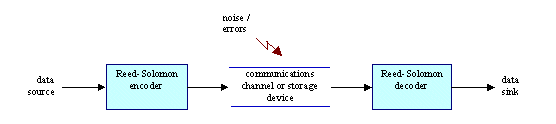
A typical system is shown here:

The Reed-Solomon encoder takes a block of digital data and adds extra “redundant” bits. Errors occur during transmission or storage for a number of reasons (for example noise or interference, scratches on a CD, etc). The Reed-Solomon decoder processes each block and attempts to correct errors and recover the original data. The number and type of errors that can be corrected depends on the characteristics of the Reed-Solomon code.

Properties of Reed-Solomon codes

Reed Solomon codes are a subset of BCH codes and are linear block codes. A Reed-Solomon code is specified as RS(n,k) with s-bit symbols.

This means that the encoder takes k data symbols of s bits each and adds parity symbols to make an n symbol codeword. There are n-k parity symbols of s bits each. A Reed-Solomon decoder can correct up to t symbols that contain errors in a codeword, where 2t = n-k.

The following diagram shows a typical Reed-Solomon codeword (this is known as a Systematic code because the data is left unchanged and the parity symbols are appended):

The following diagram shows a typical Reed-Solomon codeword (this is known as a Systematic code because the data is left unchanged and the parity symbols are appended):

Given a symbol size s, the maximum codeword length (n) for a Reed-Solomon code is n = 2s – 1

Reed-Solomon codes may be shortened by (conceptually) making a number of data symbols zero at the encoder, not transmitting them, and then re-inserting them at the decoder.

The amount of processing “power” required to encode and decode Reed-Solomon codes is related to the number of parity symbols per codeword. A large value of t means that a large number of errors can be corrected but requires more computational power than a small value of t.

Symbol Errors

One symbol error occurs when 1 bit in a symbol is wrong or when all the bits in a symbol are wrong.

Reed-Solomon codes are particularly well suited to correcting burst errors (where a series of bits in the codeword are received in error).

Decoding

Reed-Solomon algebraic decoding procedures can correct errors and erasures. An erasure occurs when the position of an erred symbol is known. A decoder can correct up to t errors or up to 2t erasures. Erasure information can often be supplied by the demodulator in a digital communication system, i.e. the demodulator “flags” received symbols that are likely to contain errors.

When a codeword is decoded, there are three possible outcomes:

1. If 2s + r < 2t (s errors, r erasures) then the original transmitted code word will always be recovered,

OTHERWISE

2. The decoder will detect that it cannot recover the original code word and indicate this fact.

OR

3. The decoder will mis-decode and recover an incorrect code word without any indication.

The probability of each of the three possibilities depends on the particular Reed-Solomon code and on the number and distribution of errors.

Coding Gain

The advantage of using Reed-Solomon codes is that the probability of an error remaining in the decoded data is (usually) much lower than the probability of an error if Reed-Solomon is not used. This is often described as coding gain.

Architectures for Encoding & Decoding Reed-Solomon Codes

Reed-Solomon encoding and decoding can be carried out in software or in special-purpose hardware.

Finite (Galois) Field Arithmetic

Reed-Solomon codes are based on a specialist area of mathematics known as Galois fields or finite fields. A finite field has the property that arithmetic operations (+,-,x,/ etc.) on field elements always have a result in the field. A Reed-Solomon encoder or decoder needs to carry out these arithmetic operations. These operations require special hardware or software functions to implement.

Generator Polynomial

A Reed-Solomon codeword is generated using a special polynomial. All valid codewords are exactly divisible by the generator polynomial. The general form of the generator polynomial is:

and the codeword is constructed using:

c(x) = g(x).i(x)

where g(x) is the generator polynomial, i(x) is the information block, c(x) is a valid codeword and a is referred to as a primitive element of the field.

Encoder architecture

The 2t parity symbols in a systematic Reed-Solomon codeword are given by:
The following diagram shows an architecture for a systematic RS(255,249) encoder:

Each of the 6 registers holds a symbol (8 bits). The arithmetic operators carry out finite field addition or multiplication on a complete symbol.

Decoder architecture

A general architecture for decoding Reed-Solomon codes is shown in the following diagram

Key

r(x) Received codeword
Si Syndromes
L(x) Error locator polynomial
Xi Error locations
Yi Error magnitudes
c(x) Recovered code word
v Number of errors

The received codeword r(x) is the original (transmitted) codeword c(x) plus errors:

r(x) = c(x) + e(x)

A Reed-Solomon decoder attempts to identify the position and magnitude of up to t errors (or 2t erasures) and to correct the errors or erasures.

Syndrome Calculation

This is a similar calculation to parity calculation. A Reed-Solomon codeword has 2t syndromes that depend only on errors (not on the transmitted code word). The syndromes can be calculated by substituting the 2t roots of the generator polynomial g(x) into r(x).

Finding the Symbol Error Locations

This involves solving simultaneous equations with t unknowns. Several fast algorithms are available to do this. These algorithms take advantage of the special matrix structure of Reed-Solomon codes and greatly reduce the computational effort required. In general two steps are involved:

Find an error locator polynomial

This can be done using the Berlekamp-Massey algorithm or Euclid’s algorithm. Euclid’s algorithm tends to be more widely used in practice because it is easier to implement: however, the Berlekamp-Massey algorithm tends to lead to more efficient hardware and software implementations.

Find the roots of this polynomial

This is done using the Chien search algorithm.

Finding the Symbol Error Values

Again, this involves solving simultaneous equations with t unknowns. A widely-used fast algorithm is the Forney algorithm.

Implementation of Reed-Solomon encoders and decoders

Hardware Implementation

A number of commercial hardware implementations exist. Many existing systems use “off-the-shelf” integrated circuits that encode and decode Reed-Solomon codes. These ICs tend to support a certain amount of programmability (for example, RS(255,k) where t = 1 to 16 symbols). A recent trend is towards VHDL or Verilog designs (logic cores or intellectual property cores). These have a number of advantages over standard ICs. A logic core can be integrated with other VHDL or Verilog components and synthesized to an FPGA (Field Programmable Gate Array) or ASIC (Application Specific Integrated Circuit) – this enables so-called “System on Chip” designs where multiple modules can be combined in a single IC. Depending on production volumes, logic cores can often give significantly lower system costs than “standard” ICs. By using logic cores, a designer avoids the potential need to do a “lifetime buy” of a Reed-Solomon IC.

Software Implementation

Until recently, software implementations in “real-time” required too much computational power for all but the simplest of Reed-Solomon codes (i.e. codes with small values of t). The major difficulty in implementing Reed-Solomon codes in software is that general purpose processors do not support Galois field arithmetic operations. For example, to implement a Galois field multiply in software requires a test for 0, two log table look-ups, modulo add and anti-log table look-up. However, careful design together with increases in processor performance mean that software implementations can operate at relatively high data rates. The following table gives some example benchmark figures on a 166MHz Pentium PC:

Code Data rate
RS(255,251) 12 Mbps
RS(255,239) 2.7 Mbps
RS(255,223) 1.1 Mbps

These data rates are for decoding only: encoding is considerably faster since it requires less computation.

First Commercial 100GE Systems

Unlike the “race to 10Gbps” that was driven by the imminent needs to address growth pains of Internet in late 1990s, customer interest to 100Gbps technologies was mostly driven by economy factors. Among those, the commonly reasons to adopt 100GE were :

  • Reduction in number of lambdas, ability to stopgap proliferation of lit fiber
  • Better bandwidth utilization relative to 10Gbps link aggregates
  • Cheaper wholesale, internet peering and datacenter interconnect connectivity
  • Desire to “skip” the relatively expensive 40Gbps technology and move directly from 10Gbps to 100Gbps

Considering that 100GE technology is natively compatible with OTN hierarchy and there is no separate adaptation for SONET/SDH and Ethernet networks, it was widely believed that 100GE technology adoption will be driven by products in all network layers, from transport systems to edge routers and datacenter switches. Nevertheless, in 2011 components for 100GE networks were not a commodity and most vendors entering this market relied on both internal R&D projects and extensive cooperation with other companies.

Optical Transport Systems

Solving the challenges of optical signal transmission over nonlinear medium is principally and analog design problem and as such evolves slower relative to digital circuit lithography progress closely fitting the Moore’s law. This explains why 10Gbps transport systems were around since mid-1990s, while first forays into 100Gbps transmission happened almost 15 years later. Nevertheless, as of Aug 2011 at least four firms (Ciena, Alcatel-Lucent, MRV, ADVA Optical and Huawei) have made customer announcements for 100Gbps transport systems – although with varying degrees of capabilities. Although most vendors claim that 100Gbps lightpaths can utilize existing analog optical infrastrure, in practice deployment of new, high-speed lambdas remains tightly controlled and extensive interoperability tests are required before moving new capacity into service.

Routers and switches with 100GE interfaces

Design of router or switch with support for 100Gbps interfaces is not an easy feat for multiple reasons. One of them is the need to process a 100Gbps stream of packets at line rate without reordering within IP/MPLS microflows. As of 2011, most components in the 100Gbps packet processing path (PHY chips, NPUs, memories) were not readily available off the shelf or require extensive qualification and co-design. Another problem is related to the low-output production of 100Gbps optical components, which were also not easily available – especially in pluggable, long-reach or tunable laser flavors. Therefore, in the early days of 100GE, vendors considered this market to be a technology showcase and were not shy to advertise their technological prowess.

In the below historical breakdown of 100GE routing and switching milestones, we keep separate track for the dates of product announcements, trials and revenue shipments (where known).

Alcatel-Lucent

Alcatel-Lucent first announced 100GbE interfaces for their 7450 ESS/7750 SR platform in June 2009, with field trials following in June-September 2010. However, in April 2011 presentation, James Watt (ALU optical division president) still mentioned 100GE technology as “demo” staged for T-Systems and Portugal Telecom. Later, in a June 2011 press-release with Verizon, the company again referenced 100GE as “trial” Thus, despite of being able to bundle the self-developed optical and routing system, Alcatel apparently missed the chance to book early revenue with 100GE deployments.

In a separate press release from June 2011, Alcatel-Lucent announced the new generation of packet processing silicon dubbed FP3, which may hint towards company’s strategy and timeline on commercial shipments of 100GE products.

Brocade

In September 2010, Brocade announced their first 100GbE solution to be based on the former Foundry Networks hardware (MLXe). Quite impressively, in June 2011 (less than a year from initial press statement), the new product went live at AMS-IX traffic exchange point in Amsterdam, bringing first-ever 100GE revenue for Brocade. This feat is even more impressive considering that Brocade commonly uses 3rd party network processors and optics. Rumored to be priced around $100K per port, the 2x 100GE linecard for MLXe appears geared for aggressive competition, although it is still unknown whether this product is capable to perform beyond IP peering applications or support long-haul / tunable optics.

Cisco

The joint Cisco-Comcast press release on first-ever 100GE trials went out back in 2008, however it is doubtful this transmission could approach 100Gbps speeds when using a 40Gbps/per slot CRS-1 platform for packet processing. The need to wait for the next generation of routing hardware can explain the fact that the following milestone for Cisco 100GE program did not happen until March 2010, when field trial in AT&T network added color to launch of a new CRS-3 router. The first 100GE deployments at AT&T and Comcast happened 12 months later, in April 2011. In addition, later in the same year, Cisco have tested the 100GE interface between CRS-3 and the next generation of their ASR9K edge router, although offering no information on hardware availability for the latter.

Huawei

In October 2008, the South-East Asian vendor presented the “industry’s first” 100GE interface for their flagship router, NE5000e . Almost a year later, in September 2009, Huawei also presented an end-to-end 100G solution consisting of OSN6800/8800 optical transport and 100GE ports on NE5000e . This time, it was also mentioned that Huawei’s solution had the new self-developed NPU “Solar 2.0 PFE2A” onboard and was using pluggable optics in CFP form-factor. In a mid-2010 solution brief, the new NE5000e linecards were given commercial name (LPUF-100) and were credited with using two Solar-2.0 NPUs per 100GE port in opposite (ingress/egress) configuration. Nevertheless, in October 2010, the company referenced shipments of NE5000e to Russian cell operator “Megafon” as “40Gbps/slot” solution, with “scalability up to” 100Gbps.

April 2011 brought a new 100GE announcement from Huawei – now the NE5000e platform was updated to carry 2x100GE interfaces per slot using LPU-200 linecards. In a related solution brief, Huawei reported 120 thousand 20G/40G Solar 1.0 chips as shipped to customers, but no Solar 2.0 numbers were given. Also, following the August 2011 100G trial in Russia, Huawei reported paying 100G DWDM customers, but no 100GE shipments on NE5000e.

Juniper Networks

Juniper first announced the 100GE to come to its T-series routers in June 2009. By this time, the latest incarnation of T-series, known as T1600 has been shipping for almost two years and supported the 100Gbit linecards in 10x10GE configuration. The 1x100GE option followed in Nov 2010, when a joint press release with academic backbone network Internet2 marked the first production 100GE interfaces going live in real network. Later in the same year, Juniper demoed 100GE operation between core (T-series) and edge (MX 3D) routers. Juniper confirmed it’s grip of the market again in March 2011, stealing thunder from Cisco by announcing first shipments of 100GE interfaces to a major North American service provider (Verizon). In the meanwhile, the company was apparently busy selling 100GE cards to a host of smaller operators (such as UK’s JANET).


Overall, it seems like Juniper was the only company recognizing meaningful revenue in 100GE market in 2010, with Brocade and Cisco joining mid-2011. Other network vendors seem to have missed the initial round of 100GE deployments.

100 Gigabit Ethernet

40 Gigabit Ethernet, or 40GbE, and 100 Gigabit Ethernet, or 100GbE, are high-speed computer network standards developed by the Institute of Electrical and Electronics Engineers (IEEE). They support sending Ethernet frames at 40 and 100 gigabits per second over multiple 10 Gb/s or 25 Gb/s lanes. Previously, the fastest published Ethernet standard was 10 Gigabit Ethernet. They were first studied in November 2007, proposed as IEEE 802.3ba in 2008, and ratified in June 2010. Another variant was added in March 2011.

History

In June 2007 a trade group called “Road to 100G” was formed after the NXTcomm trade show in Chicago. Official standards work was started by IEEE 802.3 Higher Speed Study Group. The P802.3ba Ethernet Task Force commenced on December 5, 2007 with the following project authorization request:

The purpose of this project is to extend the 802.3 protocol to operating speeds of 40 Gb/s and 100 Gb/s in order to provide a significant increase in bandwidth while maintaining maximum compatibility with the installed base of 802.3 interfaces, previous investment in research and development, and principles of network operation and management. The project is to provide for the interconnection of equipment satisfying the distance requirements of the intended applications.

Physical Standards

The 40/100 Gigabit Ethernet standards encompass a number of different Ethernet physical layer (PHY) specifications. A networking device may support different PHY types by means of pluggable modules. Optical modules are not standardized by any official standards body but are in multi-source agreements (MSAs). One agreement that supports 40 and 100 Gigabit Ethernet is the C Form-factor Pluggable (CFP) MSA which was adopted for distances of 100+ meters. QSFP and CXP connector modules support shorter distances.

The standard supported only full-duplex operation. Other electrical objectives include:

  • Preserve the 802.3 / Ethernet frame format utilizing the 802.3 MAC
  • Preserve minimum and maximum FrameSize of current 802.3 standard
  • Support a bit error ratio (BER) better than or equal to 10 − 12 at the MAC/PLS service interface
  • Provide appropriate support for OTN
  • Support MAC data rates of 40 and 100 Gbit/s
  • Provide Physical Layer specifications (PHY) for operation over single-mode optical fiber (SMF), laser optimized multi-mode optical fiber (MMF) OM3 and OM4, copper cable assembly, and backplane.

The following nomenclature was used for the physical layers:

Physical layer

40 Gigabit Ethernet

100 Gigabit Ethernet

at least 1 m over a backplane 40GBASE-KR4
approximately 7 m over copper cable 40GBASE-CR4 100GBASE-CR10
at least 100 m over OM3 MMF 40GBASE-SR4 100GBASE-SR10
at least 125 m over OM4 MMF
at least 10 km over SMF 40GBASE-LR4 100GBASE-LR4
at least 40 km over SMF 100GBASE-ER4
serial SMF over 2 km 40GBASE-FR

The 100 m laser optimized multi-mode fiber (OM3) objective was met by parallel ribbon cable with 850 nm wavelength 10GBASE-SR like optics (40GBASE-SR4 and 100GBASE-SR10). The 1 m backplane objective with 4 lanes of 10GBASE-KR type PHYs (40GBASE-KR4). The 10 m copper cable objective is met with 4 or 10 differential lanes using SFF-8642 and SFF-8436 connectors. The 10 and 40 km 100G objectives with four wavelengths (around 1310 nm) of 25G optics (100GBASE-LR4 and 100GBASE-ER4) and the 10 km 40G objective with four wavelengths (around 1310 nm) of 10G optics (40GBASE-LR4).

In January 2010 another IEEE project authorization started a task force to define a 40 gigabit per second serial single-mode optical fiber standard (40GBASE-FR). This was approved as standard 802.3bg in March 2011. It used 1550 nm optics, had a reach of 2 km and was capable of receiving 1550 nm and 1310 nm wavelengths of light. The capability to receive 1310 nm light allows it to inter-operate with a longer reach 1310 nm PHY should one ever be developed. 1550 nm was chosen as the wavelength for 802.3bg transmission to make it compatible with existing test equipment and infrastructure.

In December 2010, a 10×10 Multi Source Agreement (10×10 MSA) began to define an optical Physical Medium Dependent (PMD) sublayer and establish compatible sources of low-cost, low-power, pluggable optical transceivers based on 10 optical lanes at 10 gigabits/second each. The 10×10 MSA was intended as an lower cost alternative to 100GBASE-LR4 for applications which do not require a link length longer than 2 km. It was intended for use with standard single mode G.652.C/D type low water peak cable with ten wavelengths ranging from 1523 to 1595 nm. The founding members were Google, Brocade Communications, JDSU and Santur. Other member companies of the 10×10 MSA included MRV, Enablence, Cyoptics, AFOP, OPLINK, Hitachi Cable America, AMS-IX, EXFO, Huawei, Kotura, Facebook and Effdon when the 2 km specification was anounced in March 2011. The 10X10 MSA modules were intended to be the same size as the C Form-factor Pluggable specifications.

Backplane

NetLogic Microsystems announced backplane modules in October 2010. This industry trend is important because standards-based 100GE interconnects may allow building optical backplanes at a fraction of price currently required by VCSEL based implementations – such as those in found in multichassis systems from Cisco (CRS) and Juniper Networks (T-series).

Copper cables

Quellan announced a test board, but no module is available.

Multimode fiber

In 2009, Mellanox and Reflex Photonics announced modules based on the CFP agreement.

Single Mode fiber

Finisar, Sumitomo Electric Industries, and OpNext  all demonstrated singlemode 40 or 100 Gigabit Ethernet modules based on the C Form-factor Pluggable agreement at the European Conference and Exhibition on Optical Communication in 2009.

Compatibility

  • Optical domain IEEE 802.3ba implementations were not compatible with the numerous 40G and 100G line rate transport systems which feature different optical layer and modulation formats.
  • In particular, existing 40 Gigabit transport solutions that used dense wavelength-division multiplexing to pack four 10 Gigabit signals into one optical medium were not compatible with the IEEE 802.3ba standard, which used either coarse WDM in 1310 nm wavelength region with four 25 Gigabit or four 10 Gigabit channels, or parallel optics with four or ten optical fibers per direction

Test and Measurement

  • Ixia developed Physical Coding Sublayer Lanes and announced test equipment in 2009.
  • JDS Uniphase introduced test and measurement products for 40 and 100 Gigabit Ethernet in 2009. Discovery Semiconductors introduced optoelectronics converters for 100 gigabit testing of the 10 km and 40 km Ethernet standards.
  • Spirent Communications introduced test and measurement products in 2009 and 2010. Xena Networks demonstrated test equipment at the Technical University of Denmark in January 2011. EXFO demonstrated interoperability in January 2010.
  • These products verify Ethernet protocol implementation but do not test physical layer compliance to IEEE PMD specifications.


Standardization Time Line

IEEE standardization project history:

  • Call for interest at IEEE 802.3 plenary meeting in San Diego — July 18, 2006
  • First HSSG study group meeting — September 2006
  • Last study group meeting — November 2007
  • Task Force formally approved as P802.3ba by IEEE LMSC — December 5, 2007
  • First P802.3ba task force meeting — January 2008
  • IEEE 802.3 working group ballot — March 2009
  • IEEE LMSC sponsor ballot — November 2009
  • First 40 Gbit/s Ethernet Single-mode Fiber PMD study group meeting — January 2010.
  • P802.3bg task force approved for 40 Gbit/s serial SMF PMD— March 25, 2010
  • IEEE 802.3ba standard approved — June 17, 2010
  • IEEE 802.3bg standard approved — March 2011
  • IEEE 802.3bj 100 Gb/s Backplane and Copper Cable Task Force PAR approval due — September 2011

P802.3ba Task Force draft release dates:

  • Draft 1.0 — October 1, 2008
  • Draft 1.1 — December 9, 2008
  • Draft 1.2 — February 10, 2009
  • Draft 2.0 — March 12, 2009 (for working group ballot)
  • Draft 2.1 — May 29, 2009
  • Draft 2.2 — August 15, 2009
  • Draft 2.3 — October 14, 2009
  • Draft 3.0 — November 18, 2009 (for sponsor group ballot)
  • Draft 3.1 — February 10, 2010
  • Draft 3.2 — March 24, 2010
  • Final — June 17, 2010

Reed Solomon Code

Code

% MATLAB Code for RS coding and decoding

clc;
clear all;
close all;

n=7; k=3; % Codeword and message word lengths
m=3; % Number of bits per symbol
msg = gf([5 2 3; 0 1 7;3 6 1],m) % Two k-symbol message words
% message vector is defined over a Galois field where the number must
%range from 0 to 2^m-1

codedMessage = rsenc(msg,n,k) % Two n-symbol codewords

dmin=n-k+1 % display dmin
t=(dmin-1)/2 % diplay error correcting capability of the code

% Generate noise – Add 2 contiguous symbol errors with first word;
% 2 discontiguous symbol errors with second word and 3 distributed symbol
% errors to last word
noise=gf([0 0 0 2 3 0 0 ;6 0 1 0 0 0 0 ;5 0 6 0 0 4 0],m)

received = noise+codedMessage

%dec contains the decoded message and cnumerr contains the number of
%symbols errors corrected for each row. Also if cnumerr(i) = -1 it indicates
%that the ith row contains unrecoverable error
[dec,cnumerr] = rsdec(received,n,k)
% print the original message for comparison
msg

Output

msg = GF(2^3) array. Primitive polynomial = D^3+D+1 (11 decimal)

Array elements =

5           2           3
0           1           7
3           6           1

codedMessage = GF(2^3) array. Primitive polynomial = D^3+D+1 (11 decimal)

Array elements =

5           2           3           5           4           4           2
0           1           7           6           6           0           7
3           6           1           7           4           0           2

dmin =

5

t =

2

noise = GF(2^3) array. Primitive polynomial = D^3+D+1 (11 decimal)

Array elements =

0           0           0           2           3           0           0
6           0           1           0           0           0           0
5           0           6           0           0           4           0

received = GF(2^3) array. Primitive polynomial = D^3+D+1 (11 decimal)

Array elements =

5           2           3           7           7           4           2
6           1           6           6           6           0           7
6           6           7           7           4           4           2

dec = GF(2^3) array. Primitive polynomial = D^3+D+1 (11 decimal)

Array elements =

5           2           3
0           1           7
6           6           7

cnumerr =

2
2
-1

msg = GF(2^3) array. Primitive polynomial = D^3+D+1 (11 decimal)

Array elements =

5           2           3
0           1           7
3           6           1

System Diagrams for different standards of Ethernet

64B/66B Block Coding

Code

% 64B/66B Block Encoding

close all;

clear all;

clc;

msg = randint(1,64)

t1 = 0:63;

t2 = 0:65;

pre=input(‘whether Data (0) or Control+Data Bits (1) ‘);

if pre == 0

code = [ 0 1 msg]

else

code = [ 1 0 msg]

end

figure

subplot(2,1,1)

stairs(t1, msg,’b’)

xlabel(‘Number of bits’)

ylabel(‘Amplitude’)

title(’64B/66B Block Coding’)

legend(’64B’)

grid on;

hold on;

subplot(2,1,2)

stairs(t2, code,’g’)

grid on;

legend(’66B’)

title(’64B/66B Block Coding’)

xlabel(‘Number of bits’)

ylabel(‘Amplitude’)

Output

msg =

Columns 1 through 11

1     1     0     1    0     0     0     0     0     0    0

Columns 12 through 22

0    0     1     0    1     1     0    1     0     0     0

Columns 23 through 33

1     1     0     0    1     1     0    0     1     0    0

Columns 34 through 44

0    0     1     1     0     1     1     1    0     1     1

Columns 45 through 55

1    1     1     1     0     0     0    0     1     0    0

Columns 56 through 64

0     0     1     0    1     1     1     0     0

whether Data (0) or Control+Data Bits (1) 0

code =

Columns 1 through 11

0     1     1     1     0     1     0     0     0     0     0

Columns 12 through 22

0     0     0     0     1     0     1     1     0     1     0

Columns 23 through 33

0    0     1     1     0     0     1     1     0    0     1

Columns 34 through 44

0     0     0     0     1     1     0     1     1     1     0

Columns 45 through 55

1     1     1     1     1     1     0     0     0     0     1

Columns 56 through 66

0     0     0     0     1     0     1     1     1     0     0