Speed Matters: How Ethernet Went From 3 Mbps to 100 Gbps… and Beyond

Archive for August, 2011

GG45 Connector

The e GG45 (where GG stands for GigaGate, and 45 is to remind the backward compatibility with the 8P8C modular connector- often colloquially called RJ45) is a connector for high-speed Category 7 cable (generally known as Cat 7) LAN  cabling developed by Nexans.

The cabling system was standardized in 2001 as IEC 60603-7-7, and then selected as a worldwide Category 7 cabling standard within ISO-11801.

GG45 connectors provide backwards compatibility for standard 8P8C (RJ45) connectors in a Category 6 Cable interface (mode 1), where eight conductors are used for Cat 6 (100/250 MHz) operation.

In addition, GG45 has four additional conductors in the extreme corners that interface with new high-speed Cat. 7 600MHz and Cat 7a 1000MHz networks. The 4 additional conductors are connected to 2 pairs while the other 2 twisted pairs remain connected to the original RJ45 connector’s most distant pins: 1 and 2; and 7 and 8. A Category 6 or 6A plug uses the original contact positions, but a Category 7 or 7A plug instead uses the contacts located in the four corners and has a protrusion that activates a switch within the jack for the alternative contact positions. This reduces crosstalk within the connector that higher speed data is sensitive to. The key advantage of the GG45 interface therefore has plenty of headroom combined with the ability to migrate to higher speed service by upgrading to Category 7A patch cords that activate the switch in the jack.


RJ 45 Connector

RJ45 is a registered jack, which specifies the physical male and female connectors as well as the pin assignments of the wires in a telephone cable. The “RJ45” physical connector is standardized as the IEC 60603-7 8P8C modular connector with different “categories” of performance, with all eight conductors present but 8P8C is commonly known as RJ45. The physical dimensions of the connectors are specified in ANSI/TIA-1096-A and ISO-8877 standards.

Before the name RJ45 was used to refer to computer networking connectors, the connector was originally a  telephone-only standard. Telephone installers who wired telephone jacks were familiar with the pin assignments of Registered Jack standards. However, the physical connectors also became ubiquitous for computer networking, and informally inherited the name RJ45. A similar standard jack once used for modem/data connections, the RJ45S, uses a “keyed” variety of the 8P body with an extra tab that prevents it mating with other connectors; the visual difference compared to the more common 8P8C is subtle but is a different connector. The original RJ45S used a special keyed 8P2C modular connector, with pins 5 and 4 wired for tip and ring of a single telephone line and pins 7 and 8 shorting a programming resistor, but is obsolete today.

Understandably, because telephone RJ61X and modem RJ45S 8P2C connectors never saw wide usage and computer 8P8C connectors are quite well known today, RJ45 is (erroneously) used almost exclusively to refer to Ethernet type computer connectors. Electronics catalogs commonly advertise 8P8C modular connectors as “RJ45”, but of course an installer can wire the jack to any pin-out or use it as part of a generic structured cabling system such as ISO/IEC 15018 or ISO/IEC 11801 using RJ45 patch panels for both phone and data. Virtually all electronic equipment which uses an 8P8C connector (or possibly any 8P connector at all) will document it as an “RJ45” connector. In common usage, RJ45 also refers to the pin assignments for the attached cable, which are actually defined as T568A and T56B in wiring standards such as TIA/EIA-568-B.

RJ-45

The RJ-45 connector is commonly used for network cabling and for telephony applications.  It’s also used for serial connections in special cases.  Here’s a look at it:

Pinout for Ethernet

Although used for a variety of purposes, the RJ-45 connector is probably most commonly used for 10Base-T and 100Base-TX Ethernet connections.

Pin # Ethernet 10BASE-T
100BASE-TX

EIA/TIA 568A

EIA/TIA 568B or AT&T 258A

1 Transmit + White with green strip White with orange stripe
2 Transmit – Green with white stripe or solid green Orange with white stripe or solid orange
3 Receive + White with orange stripe White with green stripe
4 N/A Blue with white stripe or solid blue Blue with white stripe or solid blue
5 N/A White with blue stripe White with blue stripe
6 Receive – Orange with white stripe or solid orange Green with white stripe or solid
7 N/A White with brown strip or solid brown White with brown strip or solid brown
8 N/A Brown with white stripe or solid brown. Brown with white stripe or solid brown.

Because only two pairs of wires in the eight-pin RJ-45 connector are used to carry Ethernet signals, and both 10BASE-T and 100BASE-TX use the same pins, a crossover cable made for one will also work with the other.

Also, please note that it is very important that a single pair be used for pins 3 and 6.  If one conductor from one pair is used for pin 3 and a conductor from another pair is used for pin 6, performance will degrade.  See the following figure.

RJ-45 Pinout for RocketPort

The following chart shows the pinout for RJ-45 connectors used on certain RocketPort serial interface cards (manufactured by Comtrol).

Pin Name/Description
1  Request To Send
2 Data Terminal Ready
3 Ground
4 Transmit Data
5 Receive Data
6 Data Carrier Detect
7 Data Set Ready
8 Clear To Send

Pinouts for ISDN

Here’s an ISDN BRI U port pinout for a Cisco 750 series router:

Pin Function
1  Not used
2  Not used
3  Not used
4  U interface network connection (tip)
5  U interface network connection (ring)
6  Not used
7  Power (pass-through to S connector)
8  Ground (pass-through to S connector) 

The following chart shows the pinout for RJ-45 connectors used on certain ISDN S/T interfaces.  For more info, see ANSI T1.605.

Pin Color Name/Description
1  White/Orange  N/A
2  Orange  N/A
3  White/Green  Receive+
4  Blue  Transmit +
5  White/Blue  Transmit –
6  Green  Receive –
7  White/Brown   -48VDC (optional)
8  Brown  -48VDC Return (optional)


Reference:

http://www.nullmodem.com/RJ-45.htm

Copper Wire and Its Limitations

Due to the electrical properties of copper wiring, data signals will undergo some corruption during their travels.Signal corruption within certain limits is acceptable, but if the electrical properties of the cable will cause serious distortion of the signal, that cable must be replaced or repaired.

As a signal propagates down a length of cable, it loses some of its energy. So, a signal that starts out with a certain input voltage, will arrive at the load with a reduced voltage level. The amount of signal loss is known as attenuation, which is measured in decibels, or dB. If the voltage drops too much, the signal may no longer be useful.

Attenuation has a direct relationship with frequency and cable length. The high frequency used by the network, the greater the attenuation. Also, the longer the cable, the more energy a signal loses by the time it reaches the load.

A signal losses energy during its travel because of electrical properties at work in the cable. For example, every conductor offers some dc resistance to a current (sometimes called copper losses). The longer the cable, the more resistance it offers.

Resistance reduces the amount of signal passing through the wires – it does not alter the signal. Reactance, inductive or capacitive, distorts the signal.

The two concerns of signal transmission are:

  1. That enough signal gets through. (Quantity)
  2. That the signal is not distorted. (Quality)

All About Ethernet

Ethernet is a family of computer networking technologies for local area networks (LANs) commercially introduced in 1980. Standardized in IEEE 802.3, Ethernet has largely replaced competing wired LAN technologies.

Systems communicating over Ethernet divide a stream of data into individual packets called frames. Each frame contains source and destination addresses and error-checking data so that damaged data can be detected and re-transmitted.

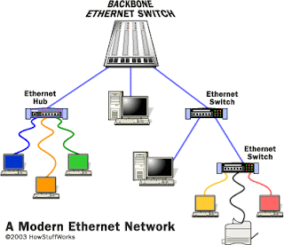
The standards define several wiring and signaling variants. The original 10BASE5 Ethernet used coaxial cable as a shared medium. Later the coaxial cables were replaced by twisted pair and fiber optic links in conjunction with hubs or switches. Data rates were periodically increased from the original 10 megabits per second, to 100 gigabits per second.

Since its commercial release, Ethernet has retained a good degree of compatibility. Features such as the 48-bit MAC address and Ethernet frame format have influenced other networking protocols.

History

Ethernet was developed at Xerox PARC between 1973 and 1975. It was inspired by ALOHAnet, which Robert Metcalfe had studied as part of his Ph.D. dissertation. In 1975, Xerox filed a patent application listing Metcalfe, David Boggs, Chuck Thacker and Butler Lampson as inventors. In 1976, after the system was deployed at PARC, Metcalfe and Boggs published a seminal paper.

Metcalfe left Xerox in 1979 to form 3Com. He convinced Digital Equipment Corporation (DEC), Intel, and Xerox to work together to promote Ethernet as a standard. The so-called “DIX” standard, for “Digital/Intel/Xerox” specified 10 Mbit/s Ethernet, with 48-bit destination and source addresses and a global 16-bit Ethertype-type field. It was published on September 30, 1980 as “The Ethernet, A Local Area Network. Data Link Layer and Physical Layer Specifications”. Version 2 was published in November, 1982 and defines what has become known as Ethernet II. Formal standardization efforts proceeded at the same time.

Ethernet initially competed with two largely proprietary systems, Token Ring and Token Bus. These proprietary protocols soon found themselves competing in a market inundated by Ethernet products. In the process, 3Com became a major company. 3Com shipped its first 10 Mbit/s Ethernet 3C100 transceiver in March 1981, and that year started selling adapters for PDP-11s and VAXes, as well as Multibus-based Intel and Sun Microsystems computers. This was followed quickly by DEC’s Unibus to Ethernet adapter, which DEC sold and used internally to build its own corporate network, which reached over 10,000 nodes by 1986; one of the largest computer networks in the world at that time.

Through the first half of the 1980s, Ethernet’s 10BASE5 implementation used a coaxial cable 0.375 inches (9.5 mm) in diameter, later called “thick Ethernet” or “thicknet”. Its successor, 10BASE2, called “thin Ethernet” or “thinnet”, used a cable similar to cable television cable of the era. The emphasis was on making installation of the cable easier and less costly.

Shared cable Ethernet was always hard to install in offices because its bus topology was in conflict with the star topology cable plans designed into buildings for telephony. Modifying Ethernet to conform to twisted pair telephone wiring already installed in commercial buildings provided another opportunity to lower costs, expand the installed base, and leverage building design, and, thus, twisted-pair Ethernet was the next logical development in the mid-1980s, beginning with StarLAN. UTP-based Ethernet became widely deployed with the 10BASE-T standard.

While 10BASE-T links used separate pairs for transmit and receive they normally acted as half duplex links to fit within the existing design of a half duplex repeater (hub) based network using CSMA/CD. Later full duplex and autonegotiation support were added for networks with switches along with higher speeds.

Standardization

Notwithstanding its technical merits, timely standardization was instrumental to the success of Ethernet. It required well-coordinated and partly competitive activities in several standardization bodies such as the IEEE, ECMA, IEC, and finally ISO.

In February 1980, the Institute of Electrical and Electronics Engineers (IEEE) started project 802 to standardize local area networks (LAN).

The “DIX-group” with Gary Robinson (DEC), Phil Arst (Intel), and Bob Printis (Xerox) submitted the so-called “Blue Book” CSMA/CD specification as a candidate for the LAN specification. Since IEEE membership is open to all professionals, including students, the group received countless comments on this technology.

In addition to CSMA/CD, Token Ring (supported by IBM) and Token Bus (selected and henceforward supported by General Motors) were also considered as candidates for a LAN standard. Due to the goal of IEEE 802 to forward only one standard and due to the strong company support for all three designs, the necessary agreement on a LAN standard was significantly delayed.

In the Ethernet camp, it put at risk the market introduction of the Xerox Star workstation and 3Com’s Ethernet LAN products. With such business implications in mind, David Liddle (General Manager, Xerox Office Systems) and Metcalfe (3Com) strongly supported a proposal of Fritz Röscheisen (Siemens Private Networks) for an alliance in the emerging office communication market, including Siemens’ support for the international standardization of Ethernet (April 10, 1981). Ingrid Fromm, Siemens’ representative to IEEE 802, quickly achieved broader support for Ethernet beyond IEEE by the establishment of a competing Task Group “Local Networks” within the European standards body ECMA TC24. As early as March 1982 ECMA TC24 with its corporate members reached agreement on a standard for CSMA/CD based on the IEEE 802 draft. The speedy action taken by ECMA decisively contributed to the conciliation of opinions within IEEE and approval of IEEE 802.3 CSMA/CD by the end of 1982. IEEE published the 802.3 standard as a draft in 1983 and as a standard in 1985.

Approval of Ethernet on the international level was achieved by a similar, cross-partisan action with Fromm as liaison officer working to integrate International Electrotechnical Commission, TC83 and International Organization for Standardization (ISO) TC97SC6, and the ISO/IEEE 802/3 standard was approved in 1984.

Evolution

Ethernet evolved to include higher bandwidth, improved media access control methods, and different physical media. The coaxial cable was replaced with point-to-point links connected by Ethernet repeaters or switches to reduce installation costs, increase reliability, and improve management and troubleshooting. Many variants of Ethernet remain in common use.

Ethernet stations communicate by sending each other data packets: blocks of data individually sent and delivered. As with other IEEE 802 LANs, each Ethernet station is given a 48-bit MAC address. The MAC addresses are used to specify both the destination and the source of each data packet. Ethernet establishes link level connections, which can be defined using both the destination and sources addresses. On reception of a transmission, the receiver uses the destination address to determine whether the transmission is relevant to the station or should be ignored. Network interfaces normally do not accept packets addressed to other Ethernet stations. Adapters come programmed with a globally unique address.An Ethertype field in each frame is used by the operating system on the receiving station to select the appropriate protocol module (i.e. the Internet protocol module). Ethernet frames are said to be self-identifying, because of the frame type. Self-identifying frames make it possible to intermix multiple protocols on the same physical network and allow a single computer to use multiple protocols together.Despite the significant changes in Ethernet, all generations of Ethernet (excluding early experimental versions) use the same frame formats (and hence the same interface for higher layers), and can be readily interconnected through bridging.

Due to the ubiquity of Ethernet, the ever-decreasing cost of the hardware needed to support it, and the reduced panel space needed by twisted pair Ethernet, most manufacturers now build Ethernet interfaces directly into PC motherboards, eliminating the need for installation of a separate network card.

Shared media

A 1990s network interface card supporting both coaxial cable-based 10BASE2 (BNC connector, left) and twisted pair-based 10BASE-T (8P8C connector, right)

Ethernet was originally based on the idea of computers communicating over a shared coaxial cable acting as a broadcast transmission medium. The methods used were similar to those used in radio systems,with the common cable providing the communication channel likened to the Luminiferous aether in 19th century physics, and it was from this reference that the name “Ethernet” was derived.

Original Ethernet’s shared coaxial cable (the shared medium) traversed a building or campus to every attached machine. A scheme known as carrier sense multiple access with collision detection (CSMA/CD) governed the way the computers shared the channel. This scheme was simpler than the competing token ring or token bus technologies.Computers were connected to an Attachment Unit Interface (AUI) transceiver, which was in turn connected to the cable (later with thin Ethernet the transceiver was integrated into the network adapter). While a simple passive wire was highly reliable for small networks, it was not reliable for large extended networks, where damage to the wire in a single place, or a single bad connector, could make the whole Ethernet segment unusable.

Since all communications happen on the same wire, any information sent by one computer is received by all, even if that information is intended for just one destination. The network interface card interrupts the CPU only when applicable packets are received: The card ignores information not addressed to it.Use of a single cable also means that the bandwidth is shared, so that network traffic can be very slow when many stations are simultaneously active.

Collisions reduce throughput by their very nature. In the worst case, when there are lots of hosts with long cables that attempt to transmit many short frames, excessive collisions can reduce throughput dramatically. However, a Xerox report in 1980 summarized the results of having 20 fast nodes attempting to transmit packets of various sizes as quickly as possible on the same Ethernet segment. The results showed that, even for the smallest Ethernet frames (64 bytes), 90% throughput on the LAN was the norm. This is in comparison with token passing LANs (token ring, token bus), all of which suffer throughput degradation as each new node comes into the LAN, due to token waits. This report was controversial, as modeling showed that collision-based networks became unstable under loads as low as 40% of nominal capacity. Many early researchers failed to understand the subtleties of the CSMA/CD protocol and how important it was to get the details right, and were really modeling somewhat different networks (usually not as good as real Ethernet).

Repeaters and hubs

For signal degradation and timing reasons, coaxial Ethernet segments had a restricted size. Somewhat larger networks could be built by using an Ethernet repeater. Early repeaters had only 2 ports, but they gave way to 4, 6, 8, and more ports as the advantages of cabling in a star network were recognized. Early experiments with star topologies (called “Fibernet”) using optical fibeR were published by 1978.

A twisted pair Cat-3 or Cat-5 cable is used to connect 10BASE-T Ethernet

Ethernet on unshielded twisted-pair cables (UTP) began with StarLAN at 1 Mbit/s in the mid-1980s. SynOptics introduced the first twisted-pair Ethernet at 10 Mbit/s in a star-wired cabling topology with a central hub, later called LattisNet. These evolved into 10BASE-T, which was designed for point-to-point links only, and all termination was built into the device. This changed repeaters from a specialist device used at the center of large networks to a device that every twisted pair-based network with more than two machines had to use. The tree structure that resulted from this made Ethernet networks easier to maintain by preventing most faults with one peer or its associated cable from affecting other devices on the network.

Despite the physical star topology, repeater based Ethernet networks still use half-duplex and CSMA/CD, with only minimal activity by the repeater, primarily the Collision Enforcement signal, in dealing with packet collisions. Every packet is sent to every port on the repeater, so bandwidth and security problems are not addressed. The total throughput of the repeater is limited to that of a single link, and all links must operate at the same speed.

Bridging and switching

While repeaters could isolate some aspects of Ethernet segments, such as cable breakages, they still forwarded all traffic to all Ethernet devices. This created practical limits on how many machines could communicate on an Ethernet network. The entire network was one collision domain, and all hosts had to be able to detect collisions anywhere on the network. This limited the number of repeaters between the farthest nodes. Segments joined by repeaters had to all operate at the same speed, making phased-in upgrades impossible.

To alleviate these problems, bridging was created to communicate at the data link layer while isolating the physical layer. With bridging, only well-formed Ethernet packets are forwarded from one Ethernet segment to another; collisions and packet errors are isolated. Prior to discovery of network devices on the different segments, Ethernet bridges (and switches) work somewhat like Ethernet repeaters, passing all traffic between segments. However, as the bridge discovers the addresses associated with each port, it forwards network traffic only to the necessary segments, improving overall performance. Broadcast traffic is still forwarded to all network segments. Bridges also overcame the limits on total segments between two hosts and allowed the mixing of speeds, both of which became very important with the introduction of Fast Ethernet.

Early bridges examined each packet one by one using software on a CPU, and some of them were significantly slower than repeaters at forwarding traffic, especially when handling many ports at the same time. This was in part because the entire Ethernet packet would be read into a buffer, the destination address compared with an internal table of known MAC addresses, and a decision made as to whether to drop the packet or forward it to another or all segments.

In 1989, the networking company Kalpana introduced their EtherSwitch, the first Ethernet switch.This worked somewhat differently from an Ethernet bridge, in that only the header of the incoming packet would be examined before it was either dropped or forwarded to another segment. This greatly reduced the forwarding latency and the processing load on the network device. One drawback of this cut-through switching method was that packets that had been corrupted would still be propagated through the network, so a jabbering station could continue to disrupt the entire network. The eventual remedy for this was a return to the original store and forward approach of bridging, where the packet would be read into a buffer on the switch in its entirety, verified against its checksum and then forwarded, but using more powerful application-specific integrated circuits. Hence, the bridging is then done in hardware, allowing packets to be forwarded at full wire speed.

When a twisted pair or fiber link segment is used and neither end is connected to a repeater, full-duplex Ethernet becomes possible over that segment. In full-duplex mode, both devices can transmit and receive to and from each other at the same time, and there is no collision domain. This doubles the aggregate bandwidth of the link and is sometimes advertised as double the link speed (e.g., 200 Mbit/s). The elimination of the collision domain for these connections also means that all the link’s bandwidth can be used by the two devices on that segment and that segment length is not limited by the need for correct collision detection.

Since packets are typically delivered only to the port they are intended for, traffic on a switched Ethernet is less public than on shared-medium Ethernet. Despite this, switched Ethernet should still be regarded as an insecure network technology, because it is easy to subvert switched Ethernet systems by means such as ARP spoofing and MAC flooding.

The bandwidth advantages, the slightly better isolation of devices from each other, the ability to easily mix different speeds of devices and the elimination of the chaining limits inherent in non-switched Ethernet have made switched Ethernet the dominant network technology.

Advanced networking

Simple switched Ethernet networks, while a great improvement over repeater-based Ethernet, suffer from single points of failure, attacks that trick switches or hosts into sending data to a machine even if it is not intended for it, scalability and security issues with regard to broadcast radiation and multicast traffic, and bandwidth choke points where a lot of traffic is forced down a single link.

Advanced networking features in switches and routers combat these issues through means including spanning-tree protocol to maintain the active links of the network as a tree while allowing physical loops for redundancy, port security and protection features such as MAC lock down and broadcast radiation filtering, virtual LANs to keep different classes of users separate while using the same physical infrastructure, multilayer switching to route between different classes and link aggregation to add bandwidth to overloaded links and to provide some measure of redundancy.

Networking advances IEEE 802.1aq (SPB) include the use of the link-state routing protocol IS-IS to allow larger networks with shortest path routes between devices.

Varieties of Ethernet

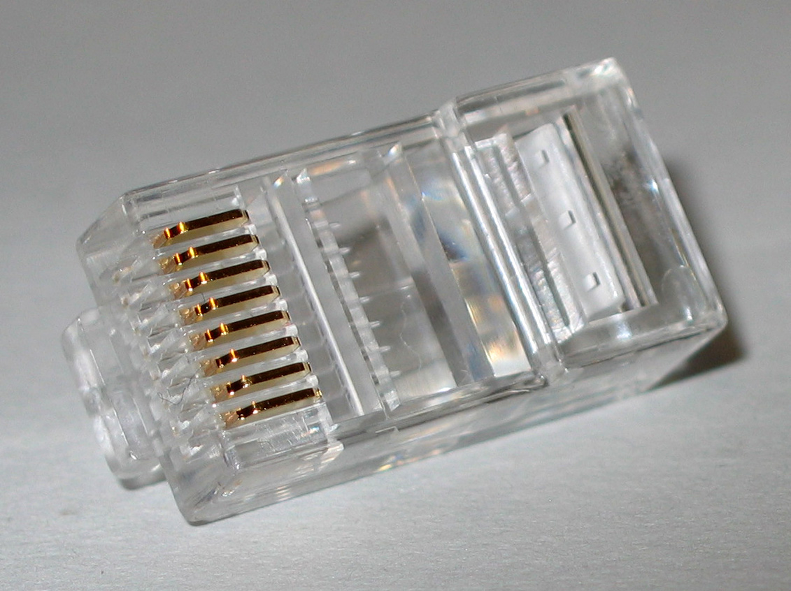
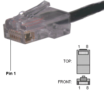
The Ethernet physical layer evolved over a considerable time span and encompasses quite a few physical media interfaces and several magnitudes of speed. The most common forms used are 10BASE-T, 100BASE-TX, and 1000BASE-T. All three utilize twisted pair cables and 8P8C modular connectors. They run at 10 Mbit/s, 100 Mbit/s, and 1 Gbit/s, respectively. Fiber optic variants of Ethernet offer high performance, electrical isolation and distance (tens of kilometers with some versions). In general, network protocol stack software will work similarly on all varieties.

Ethernet frames

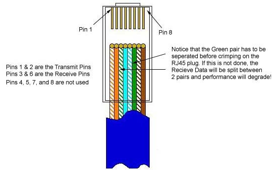
A data packet on the wire is called a frame. A frame begins with Preamble and Start Frame Delimiter, following which each Ethernet frame features an Ethernet header featuring source and destination MAC addresses. The middle section of the frame consists of payload data including any headers for other protocols (e.g., Internet Protocol) carried in the frame. The frame ends with a 32-bit cyclic redundancy check, which is used to detect any corruption of data in transit.

Autonegotiation

Autonegotiation is the procedure by which two connected devices choose common transmission parameters, such as speed and duplex mode. Autonegotiation was first introduced as an optional feature for Fast Ethernet, but it is also backward compatible with 10BASE-T. Autonegotiation is mandatory for Gigabit Ethernet.

IEEE 802.3 Communication Standards’ Chart

Ethernet Standard Date Description
Experimental
Ethernet
1973 2.94 Mbit/s (367 kB/s) over coaxial cable (coax) cable bus
Ethernet II
(DIX v2.0)
1982 10 Mbit/s (1.25 MB/s) over thick coax. Frames have a Type field. This frame format is used on all forms of Ethernet by protocols in the Internet protocol suite.
IEEE 802.3 1983 10BASE5 10 Mbit/s (1.25 MB/s) over thick coax. Same as Ethernet II (above) except Type field is replaced by Length, and an 802.2 LLC header follows the 802.3 header
802.3a 1985 10BASE2 10 Mbit/s (1.25 MB/s) over thin Coax (a.k.a. thinnet or cheapernet)
802.3b 1985 10BROAD36
802.3c 1985 10 Mbit/s (1.25 MB/s) repeater specs
802.3d 1987 Fiber-optic inter-repeater link
802.3e 1987 1BASE5 or StarLAN
802.3i 1990 10BASE-T 10 Mbit/s (1.25 MB/s) over twisted pair
802.3j 1993 10BASE-F 10 Mbit/s (1.25 MB/s) over Fiber-Optic
802.3u 1995 100BASE-TX, 100BASE-T4, 100BASE-FX Fast Ethernet at 100 Mbit/s (12.5 MB/s) w/autonegotiation
802.3x 1997 Full Duplex and flow control; also incorporates DIX framing, so there’s no longer a DIX/802.3 split
802.3y 1998 100BASE-T2 100 Mbit/s (12.5 MB/s) over low quality twisted pair
802.3z 1998 1000BASE-X Gbit/s Ethernet over Fiber-Optic at 1 Gbit/s (125 MB/s)
802.3-1998 1998 A revision of base standard incorporating the above amendments and errata
802.3ab 1999 1000BASE-T Gbit/s Ethernet over twisted pair at 1 Gbit/s (125 MB/s)
802.3ac 1998 Max frame size extended to 1522 bytes (to allow “Q-tag”) The Q-tag includes 802.1Q VLAN information and 802.1p priority information.
802.3ad 2000 Link aggregation for parallel links, since moved to IEEE 802.1AX
802.3-2002 2002 A revision of base standard incorporating the three prior amendments and errata
802.3ae 2003 10 Gbit/s (1,250 MB/s) Ethernet over fiber; 10GBASE-SR, 10GBASE-LR, 10GBASE-ER, 10GBASE-SW, 10GBASE-LW, 10GBASE-EW
802.3af 2003 Power over Ethernet (12.95 W)
802.3ah 2004 Ethernet in the First Mile
802.3ak 2004 10GBASE-CX4 10 Gbit/s (1,250 MB/s) Ethernet over twin-axial cable
802.3-2005 2005 A revision of base standard incorporating the four prior amendments and errata.
802.3an 2006 10GBASE-T 10 Gbit/s (1,250 MB/s) Ethernet over unshielded twisted pair (UTP)
802.3ap 2007 Backplane Ethernet (1 and 10 Gbit/s (125 and 1,250 MB/s) over printed circuit boards)
802.3aq 2006 10GBASE-LRM 10 Gbit/s (1,250 MB/s) Ethernet over multimode fiber
P802.3ar Cancelled Congestion management (withdrawn)
802.3as 2006 Frame expansion
802.3at 2009 Power over Ethernet enhancements (25.5 W)
802.3au 2006 Isolation requirements for Power Over Ethernet (802.3-2005/Cor 1)
802.3av 2009 10 Gbit/s EPON
802.3aw 2007 Fixed an equation in the publication of 10GBASE-T (released as 802.3-2005/Cor 2)
802.3-2008 2008 A revision of base standard incorporating the 802.3an/ap/aq/as amendments, two corrigenda and errata. Link aggregation was moved to 802.1AX.
802.3az 2010 Energy Efficient Ethernet
802.3ba 2010 40 Gbit/s and 100 Gbit/s Ethernet. 40 Gbit/s over 1m backplane, 10m Cu cable assembly (4×25 Gbit or 10×10 Gbit lanes) and 100 m of MMF and 100 Gbit/s up to 10 m of Cu cable assembly, 100 m of MMF or 40 km of SMF respectively
802.3-2008/Cor 1 2009 Increase Pause Reaction Delay timings which are insufficient for 10G/sec (workgroup name was 802.3bb)
802.3bc 2009 Move and update Ethernet related TLVs (type, length, values), previously specified in Annex F of IEEE 802.1AB (LLDP) to 802.3.
802.3bd 2010 Priority-based Flow Control. A amendment by the IEEE 802.1 Data Center Bridging Task Group (802.1Qbb) to develop an amendment to IEEE Std 802.3 to add a MAC Control Frame to support IEEE 802.1Qbb Priority-based Flow Control.
802.3.1 2011 MIB definitions for Ethernet. It consolidates the Ethernet related MIBs present in Annex 30A&B, various IETF RFCs, and 802.1AB annex F into one master document with a machine readable extract. (workgroup name was P802.3be)
802.3bf 2011 Provide an accurate indication of the transmission and reception initiation times of certain packets as required to support IEEE P802.1AS.
802.3bg 2011 Provide a 40 Gbit/s PMD which is optically compatible with existing carrier SMF 40 Gbit/s client interfaces (OTU3/STM-256/OC-768/40G POS).
P802.3ah ~Mar 2012 A revision of base standard incorporating the 802.3at/av/az/ba/bc/bd/bf/bg amendments, a corrigenda and errata. (Expected to be published as 802.3-2012)

Network Interface Controller

A  1990s Ethernet network interface controller card which connects to the motherboard via the now-obsolete ISA bus. This combination card features both a (now obsolete) bayonet cap BNC connector (left) for use in coaxial-based 10base2 networks and an RJ-45 connector (right) for use in twisted pair-based 10baseT networks. (The ports could not be used simultaneously.)

A network interface controller (also known as a network interface card, network adapter, LAN adapter and by similar terms) is a computer hardware component that connects a computer to a computer network.

Whereas network interface controllers were commonly implemented on expansion cards that plug into a computer bus, the low cost and ubiquity of the Ethernet standard means that most newer computers have a network interface built into the motherboard.

Purpose

The network controller implements the electronic circuitry required to communicate using a specific physical layer and data link layer standard such as Ethernet, Wi-Fi, or Token Ring. This provides a base for a full network protocol stack, allowing communication among small groups of computers on the same LAN and large-scale network communications through routable protocols, such as IP.

Madge 4/16 Mbit/s TokenRing ISA-16 NIC

Although other network technologies exist (e.g. token ring), Ethernet has achieved near-ubiquity since the mid-1990s.

Every Ethernet network controller has a unique 48-bit serial number called a MAC address, which is stored in read-only memory carried on the card for add-on cards. Every computer on an Ethernet network must have at least one controller. Each controller must have a unique MAC address. Normally it is safe to assume that no two network controllers will share the same address, because controller vendors purchase blocks of addresses from the Institute of Electrical and Electronics Engineers (IEEE) and assign a unique address to each controller at the time of manufacture.

The NIC allows computers to communicate over a computer network. It is both an OSI layer 1 (physical layer) and layer 2 (data link layer) device, as it provides physical access to a networking medium and provides a low-level addressing system through the use of MAC addresses. It allows users to connect to each other either by using cables or wirelessly.

Implementation

Whereas network controllers used to operate on expansion cards that plugged into a computer bus, the low cost and ubiquity of the Ethernet standard means that most newer computers have a network interface built into the motherboard. Newer server motherboards may even have dual network interfaces built-in. The Ethernet capabilities are either integrated into the motherboard chipset or implemented via a low-cost dedicated Ethernet chip, connected through the PCI (or the newer PCI express) bus. A separate network card is not required unless additional interfaces are needed or some other type of network is used.

The NIC may use one or more of four techniques to transfer data:

  • Polling is where the CPU examines the status of the peripheral under program control.
  • Programmed I/O is where the microprocessor alerts the designated peripheral by applying its address to the system’s address bus.
  • Interrupt-driven I/O is where the peripheral alerts the microprocessor that it is ready to transfer data.
  • Direct memory access is where an intelligent peripheral assumes control of the system bus to access memory directly. This removes load from the CPU but requires a separate processor on the card.

An Ethernet network controller typically has an RJ45 socket where the network cable is connected. Older NICs also supplied BNC. or AUI connections. A few LEDs inform the user of whether the network is active, and whether or not data transmission occurs. Ethernet network controllers typically support 10 Mbit/s Ethernet, 100 Mbit/s Ethernet, and 1000 Mbit/s Ethernet varieties. Such controllers are designated 10/100/1000 – this means they can support a notional maximum transfer rate of 10, 100 or 1000 Megabits per second.

Some products feature NIC partitioning (NPAR).

Cat6 Cable Characteristics

  • Unshielded Twisted Pair cable is the most  common form of cable used for data networks.
  • The Electronic Industries Alliance  produced standards for UTP cable, recommending configuration and performance  requirements for the cable.
  • These standards grade the cable into categories.  Each category is known by a “Cat” number; “Cat6” is one of these.
  • Since February  2011, the definition of UTP categories has been the responsibility of the  Telecommunications Industry  Association.

Unshielded Twisted Pair

  • Unshielded Twisted Pair cable is a structured cable.
  • It contains eight  composite wires, each of stranded copper and protected with a color-coded  plastic jacket.
  • The eight wires are coupled into four pairs.
  • The two wires of  each pair represent the positive and negative paths of a complete  circuit.

Shielding

  • When an electric current passes along a wire, it creates a magnetic field  around the wire.
  • The twisting of these two wires brings the magnetic fields of  the two wires into contact. They cancel each other out.
  • Any environmental  magnetic interference merges with the positive or negative field around the  wires and gets wiped out along with the merger of the two magnetic fields.
  • This  is the defining characteristic of UTP. The effect of twisting the wires around  each other removes the need to include a metal shield around the wires.
  • The  absence of the shield makes the cable cheap to manufacture.
  • Its price advantage  makes it the most implemented cable type for data  networks.

Cat6

  • Cat6 wire has the same configuration as the earlier Cat5 and Cat5e (enhanced)  standards.
  • The difference with Cat6 is that it has thicker insulation — that,  is, the jacket around the cable is thicker than with earlier categories.
  • The  twisting rate is also higher.
  • Cat6 has increased protection against  interference and so can carry data faster and further without damage to the  signal from interference.

Applications

  • Cat5 and Cat5e cable are the most widely implemented forms of UTP, because  they have been around longer than Cat6.
  • UTP is one of the cable types  recommended for Ethernet networks, and because it is the cheapest form of cable  recommended by Ethernet, it is the most common form of network cable.
  • Ethernet  specifications publish complete network performance guides to enable the  construction of networks fulfilling particular performance criteria.
  • Cat5e is  able to supply the performance required by Gigabit Ethernet, however, this  category of Ethernet is better suited to Cat6 cable.
  • The category, together with  its improved version, Cat6a (advanced) can also be used for 10- and 40- gigabit  systems.

Reference:

www.ehow.com/info_10016245_cat6-cable-characteristics.html

Short History of Cat 6

Back in 1996 there were questions about whether Category 5 was going to have sufficient bandwidth to economically support all future local area network (LAN) applications.. The ATM Forum had released its 155 Mbps over copper specification, and while the TIA Category 5 specification had barely fulfilled the performance requirement, the international Class D link performance specification did not. A debate ensued. Did it make more sense to stay with Category 5, add more sophistication into the network interface cards (NICs), and employ more complex modulation and near end crosstalk (NEXT) cancellation technology to accommodate new applications with 100 MHz? Or, should a new and higher performance level for unshielded twisted pair (UTP) cabling be specified? The IEEE had begun development of a Gigabit Ethernet specification and it was uncertain if standard Category 5 would support it. (Today it appears that while some installed Category 5 links will, Category 5e is recommended.

In addition, many suppliers had developed significantly improved production processes and techniques to minimize crosstalk and improve return loss (RL). But there was no standards-approved label that could be put on this improved cabling, except to quote ‘better headroom’, or ‘higher speed performance’. This situation was creating a great deal of confusion in the marketplace.

At a pivotal International Standards Organization (ISO) meeting in Munich in September of 1997, it was decided to concurrently develop a 200 MHz UTP Category 6 specification and 600 MHz SSTP Category 7 specification. Category 6 was on its
way.

1989

1999

2009 

Typical PC IBM 8086 4 MHz Pentium III 400 MHz Octium V 3 GHz
RAM 64 kB 128 MB 2 GB
Mass Storage 400 kB 8.4 GB 250 GB
Network Speed 1 Mbs 100 Mbps 1 Gbps
Dial Up Speed 48 bps 56 Kbps modem; 1 Mbps or cable modem 100 Mbps
Average File Size 5 kB 500 kB 50 MB
What’s Hot Apple Mac Anything “dot com” Wireless Radio Watches

When a building is put up, the essential services (plumbing, AC, heating) are expected to last the life of the building, certainly, at a minimum, 25 years. Why should any less be expected from data cabling? The cost in labor and disruption of productivity to retrofit existing buildings with new data cabling is tremendous.

Media Analogy Max. Safe Speed Typical Data Rate @ Distance Vehicle/NIC Cost
Category 3 Primitive Road 30 mph 10 Mbps @ 100m Cheap
Category 5 Paved One Lane Road 55 mph 100 Mbps @ 100 m Cheap
Category 5e Two-lane Road 120 mph 100/1000 Mbps @ 100 m Cheap/High
Category 6 Racetrack 300 mph 1/10 Gbps @ 100 m Cheap/High
MM Fiber Sky 600 mph 1Gbps+ @2 km Medium
SM Fiber Space 20,000 mph 10 Gbps+ @ 100km High

Any given category of cabling can support high-speed data transmission, but the better the quality of the cabling, the cheaper the associated electronics. It is a lot easier to get 100 Mbps on Category 6 than on Category 3. The above table analogizes cabling categories and roadway quality, providing a clearer picture of the significance of media. Given the pace of networking progress, can there be any doubt that Category 5 will be insufficient to meet the demands of future LANs?

What is Category 6 ?

Category 6 channels have a useful bandwidth of at least 200 MHz. This means that the pair-to-pair ACR (attenuation to crosstalk ratio) will be at least 3 dB for all frequencies up to at least 200 MHz. This is also the zero Power Sum ACR point. Category 6 also has very uniform impedance and excellent RL performance. Category 6 is simply the best UTP cabling system available.

Category 6 is chiefly differentiated from Category 5 by its improved NEXT and RL performance. Good return loss is extremely important in new high-speed full duplex LAN applications. Crosstalk performance essentially controls the maximum available bandwidth since attenuation cannot be significantly improved without a large increase in conductor diameter.

The TIA TR42.5 committee is now preparing a lower cost Gigabit Ethernet hardware proposal that takes advantage of the bandwidth of Category 6 cabling.

A brief performance comparison between Category 5 and 6 based on current available draft standards is shown in the table below:

Category 5 

Category 6 

Basic Link Performance Based onTSB95 draft 12, 9/99 Based on current draft 5, 5/99
Maximum Length 94 m 94 m
NEXT Performance 29.3 dB @ 100 MHz 41.9 dB @ 100 MHz

36.9 dB @ 200 MHz

Attenuation Performance 21.6 dB @ 100 MHz 20.7 dB @ 100 MHz

30.4 dB @ 200 MHz

Return Loss Performance 1< f < 20 MHz: 15 dB 1< f < 20 MHz: 19 dB
20<f<100 MHz: 15-7log (f/20)dB 20<f<200 MHz: 19-7log (f/20)dB
ELFEXT Performance 17 dB @ 100 MHz 25.2 dB @ 100 MHz

19.2 dB @ 200 MHz

Are Category 6 products available. Absolutely. Did cabling suppliers wait patiently for TIA 568A and TSB67 before shipping Category 5 products? It’s no different today. While the standards for Category 6 are being actively developed, we are not waiting for their completion. Most manufacturers have announced Category 6 cabling, connecting hardware and field test equipment. How can these manufacturers specify Category 6 performance when no Category 6 standards exist? In many cases the manufacturers state that the products offered meet the performance requirement of currently published draft standards. In some
cases, a guarantee is provided that the product will meet the performance requirement of the final finished Category 6 standard when it is published. In almost all cases, you are dealing with reputable established companies with strong track records in structured cabling.

The biggest challenge facing Category 6 at this moment is a lack of interoperability. Because manufacturers have responded quickly with products in the absence of a standard, different methods to achieve NEXT connector cancellation have been used. These methods are, in most cases, incompatible with each other. For the purposes of illustration, a jack can be considered to have
positive crosstalk, and a plug can have negative crosstalk. When the crosstalk is opposite in magnitude and phase, it cancels and results in a low crosstalk connection.

Because Category 6 connectors must be backward compatible with Category 5, Category 6 plugs and jacks must also have positive and negative crosstalk. But since the cancellation requirements are much more stringent for Category 6, a very tight tolerance on the components is required. For this reason, it is essential at this time to maintain one supplier’s connecting hardware throughout
a given Category 6 installation.

Reference:

www.connectek.net/pages/cat6_history.htm

EIA/TIA 568 and ISO/IEC 11801 Wiring Grades

Grade 1 – Unshielded Untwisted wiring. Commonly called inside wire by the  Telco community. (Informal designation)

Grade 2 – Unshielded twisted pair (UTP) derived from IBM Type 3 spec. (Informal designation)

Category 3 – Unshielded twisted pair with 100 ohm impedance and  electrical characteristics supporting transmission at frequencies up to 16 MHz.  May be used with 10Base-T, 100Base-T4, and 100Base-T2 Ethernet. (Obsolete)

Category 4 – Unshielded twisted pair with 100 ohm impedance and  electrical characteristics supporting transmission at frequencies up to 20 MHz.  May be used with 10Base-T, 100Base-T4, and 100Base-T2 Ethernet. (Obsolete)

Category 5 – Unshielded twisted pair with 100 ohm impedance and electrical characteristics supporting transmission at frequencies up to 100 MHz. May be used with 10Base-T, 100Base-T4, 100Base-T2, and 100Base-TX Ethernet. May support 1000Base-T, but cable should be tested. (Superceded by Cat5e)

Category 5e – “Enhanced Cat 5” exceeds Cat 5 performance. Very similar to Cat 5, it has improved specifications for NEXT (Near End Cross Talk), PSELFEXT (Power Sum Equal Level Far End Cross Talk), and Attenuation. May be used for 10Base-T, 100Base-T4, 100Base-T2, 100BaseTX and 1000Base-T Ethernet. (Minimum acceptable wiring grade)

Category 6 – In June 2002 TIA approved specification for Cat 6 doubling Cat 5 bandwidth to 250 MHz. Cat 6 is backward compatible with lower Category grades and supports the same Ethernet standards as Cat 5e. A Cat 6 whitepaper is available from TIA. Currently there are no Ethernet standards that take advantage of Cat 6. ANSI/TIA854 is working on 1000Base-TX. When complete this standard will use two pair in each direction as opposed to all four for 1000Base-T over Cat 5e. This is expected to reduce the cost of Gigabit Ethernet implementations. 1000Base-TX will only operate over Cat6.

Category 7 – Proposed standard to support transmission at frequencies up to 600 MHz over 100 ohm twisted pair.

NOTES:
1) EIA 568 limits UTP copper cabling to maximum distance of 100 meters (328 feet). 90 meters of cable plus 10 meters of patch cord split between both ends.
2) The FCC recently changed the requirement for telephone inside wiring to minimum of Cat 3 due to crosstalk problems with nontwisted quad-four. Cat 3 is no longer recognized by TIA. The minimum wiring grade for structured wiring is Cat 5e.
3) For installation to meet specific Category requirements all components must meet or exceed the designated Category. Using a Cat 3 receptacle (or patch cord) on Cat 6 reduces performance to Cat 3.

Category 6 ANSI/TIA/EIA Performance Limits

Category 6 Cable Limits in dB per ANSI/TIA/EIA-568B.2-1

Frequency MHz Insertion Loss per 100m NEXT pair-to-pair NEXT power sum ELFEXT pair-to-pair ELFEXT power sum ACR pair-to-pair ACR power sum Return Loss Solid
1 2.0 74.3 72.3 67.8 64.8 72.3 70.3 20.0
4 3.8 65.3 63.3 55.8 52.8 61.5 59.5 23.0
8 5.3 60.8 58.8 49.7 46.7 55.5 53.5 24.5
10 6.0 59.3 57.3 47.8 44.8 53.3 51.3 25.0
16 7.6 56.2 54.2 43.7 40.7 48.6 46.6 25.0
20 8.5 54.8 52.8 41.8 38.8 46.3 44.3 25.0
25 9.5 53.3 51.3 39.8 36.8 43.8 41.8 24.3
31.25 10.7 51.9 49.9 37.9 34.9 41.2 39.2 23.6
62.5 15.4 47.4 45.4 31.9 28.9 32.0 30.0 21.5
100 19.8 44.3 42.3 27.8 24.8 24.5 22.5 20.1
200 29.0 39.8 37.8 21.8 18.8 10.8 8.8 18.0
250 32.8 38.3 36.3 19.8 16.8 5.5 3.5 17.3

Category 6 Connecting Hardware Limits in dB per ANSI/TIA/EIA-568B.2-1

Frequency MHz Insertion Loss NEXT pair-to-pair FEXT pair-to-pair ACR pair-to-pair Return Loss
1 0.1 75.0 75.0 74.9 30.0
4 0.1 75.0 71.1 74.9 30.0
8 0.1 75.0 65.0 74.9 30.0
10 0.1 74.0 63.1 73.9 30.0
16 0.1 69.9 59.0 69.8 30.0
20 0.1 68.0 57.1 67.9 30.0
25 0.1 66.0 55.1 65.9 30.0
31.25 0.1 64.1 53.2 64.0 30.0
62.5 0.2 58.1 47.2 57.9 28.1
100 0.2 54.0 43.1 53.8 24.0
200 0.3 48.0 37.1 47.7 18.0
250 0.3 46.0 35.1 45.7 16.0

Category 6 Channel Limits in dB per ANSI/TIA/EIA-568B.2-1

Frequency MHz Insertion Loss NEXT pair-to-pair NEXT power sum ELFEXT pair-to-pair ELFEXT power sum ACR pair-to-pair ACR power sum Return Loss
1 2.1 65.0 62.0 63.3 60.3 62.9 59.9 19.0
4 4.0 63.0 60.5 51.2 48.2 59.0 56.5 19.0
8 5.7 58.2 55.6 45.2 42.2 52.5 49.9 19.0
10 6.3 56.6 54.0 43.3 40.3 50.3 47.7 19.0
16 8.0 53.2 50.6 39.2 36.2 45.2 42.6 18.0
20 9.0 51.6 49.0 37.2 34.2 42.6 40.0 17.5
25 10.1 50.0 47.3 35.3 32.3 39.9 37.2 17.0
31.25 11.4 48.4 45.7 33.4 30.4 37.0 34.3 16.5
62.5 16.5 43.4 40.6 27.3 24.3 26.9 24.1 14.0
100 21.3 39.9 37.1 23.3 20.3 18.6 15.8 12.0
200 31.5 34.8 31.9 17.2 14.2 3.3 0.4 9.0
250 35.9 33.1 30.2 15.3 12.3 -2.8 -5.7 8.0

Category 6 Permanent Link Limits in dB per ANSI/TIA/EIA-568B.2-1

Frequency MHz Insertion Loss NEXT pair-to-pair NEXT power sum ELFEXT pair-to-pair ELFEXT power sum ACR pair-to-pair ACR power sum Return Loss
1 1.9 65.0 62.0 64.2 61.2 63.1 60.1 19.1
4 3.5 64.1 61.8 52.1 49.1 60.6 58.3 21.0
8 5.0 59.4 57.0 46.1 43.1 54.4 52.0 21.0
10 5.5 57.8 55.5 44.2 41.2 52.3 50.0 21.0
16 7.0 54.6 52.2 40.1 37.1 47.6 45.2 20.0
20 7.9 53.1 50.7 38.2 35.2 45.2 42.8 19.5
25 8.9 51.5 49.1 36.2 33.2 42.6 40.2 19.0
31.25 10.0 50.0 47.5 34.3 31.3 40.0 37.5 18.5
62.5 14.4 45.1 42.7 28.3 25.3 30.7 28.3 16.0
100 18.6 41.8 39.3 24.2 21.2 23.2 20.7 14.0
200 27.4 36.9 34.3 18.2 15.2 9.5 6.9 11.0
250 31.1 35.3 32.7 16.2 13.2 4.2 1.6 10.0