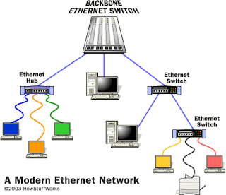
Speed Matters: How Ethernet Went From 3 Mbps to 100 Gbps… and Beyond

Archive for July, 2011

Convolutional Code

Convolutional Codes

  • In convolutional codes, redundancy is added continuously to the whole stream.
  • They depend upon the previous input.
  • The encoder keeps M previous input bits in memory.
  • Each output bit of the encoder then depends on the current input bit as well as the Mstored bits.
  • Convolutional codes are referred to as continuous codes as they operate on a certain number of bits continuously.

A convolutional code is a type of error-correcting code in which

  • each m-bit information symbol (each m-bit string) to be encoded is transformed into an n-bit symbol, where m/n is the code rate (nm), and
  • the transformation is a function of the last k information symbols, where k is the constraint length of the code.

Convolutional codes are commonly specified by three parameters; (n,k,m).

  • n = number of output bits
  • k = number of input bits
  • m = number of memory registers

The quantity k/n called the code rate, is a measure of the efficiency of the code. Commonly k and n parameters range from 1 to 8, m from 2 to 10 and the code rate from 1/8 to 7/8 except for deep space applications where code rates as low as 1/100 or even longer have been employed.

  • Often the manufacturers of convolutional code chips specify the code by parameters (n,k,L), The quantity L is called the constraint length of the code and is defined by Constraint Length, L = k (m-1).
  • The constraint length L represents the number of bits in the encoder memory that affect the generation of the n output bits.
  • The constraint length L is also referred to by the capital letter K, which can be confusing with the lower case k, which represents the number of input bits.
  • Sometimes K is defined as equal to product the of  k and m.
  • Often in commercial spec, the codes are specified by (r, K), where r = the code rate k/n and K is the constraint length.
  • The constraint length K however is equal to L – 1.

  • Convolutional codes represent one technique within thegeneral class of channel codes.
  • Channel codes (also callederror-correction codes) permit reliable communication of an information sequence over a channel that adds noise, introduces bit errors, or otherwise distorts the transmitted signal.
  • Elias introduced convolutional codes in 1955.
  • These codes have found many applications, including deep-space communications and voice band modems.
  • Convolutional codes continue to play a role in low latency applications such as speech transmission and as constituent codes in Turbo codes.

Encoder Representations

The encoder can be represented in several different but equivalent ways. They are

  1. Connection Representation
  2. Polynomial Representation
  3. State Diagram Representation
  4. Tree Diagram Representation
  5. Trellis Diagram Representation

1. Connection Representation:

2. Polynomial Representation:

For Connection representation above we can have following Generator polynomials:

g1(x) = 1 + x + x^2

g2(x) = 1 + x^2

The output Sequence is found as follows:

U(x) = m(x) g1(x) interlaced with m(x) g2(x)

3. State Diagram Representation:

  • A convolution encoder belongs to class of devices known as Finite State Machines, Which the general name is given to machines that have a memory of past signals.
  • The adjective “Finite” refers to the fact that there are only finite Number of unique states that the machine can encounter,
    What is meant by the state of the machine?
  • In most general sense the state consist of the smallest information that, together with current input to machine can predict the output of the machine.

4. The Tree Digram:

  • The Tree Diagram adds the dimension of time to state diagram.
  • At each input bit time the encoding process can be described by traversing the diagram left to right with each tree branch describing an output branch word.
  • For K=3 and Code rate= ½ we have

5. The Trellis Diagram:

The Trellis Diagram exploits a repetitive structure and a more manageable encoder description than that of Tree Diagram. See figure, the dotted line shows input bit 1 and solid line shows input bit 0.

Reference:

Block Codes

Block Codes

  • Block coding is a special case of error-control coding.
  • Block codes break the message stream into fixed-size blocks.
  • They do not depend upon the previous input.
  • Block coding techniques map a fixed number of message symbols to a fixed number of code symbols.
  • A block coder treats each block of data independently and is a memory less device.
  • Block codes operate on a block of bits. Using a preset algorithm, take a group of bits and add a coded part to make a larger
    block. This block is checked at the receiver. The receiver then makes a decision about the validity of the received sequence.
  • Block codes are referred to as (n, k) codes.
  •  A block of k information bits are coded to become a block of n bits.
  • A block code transforms a message m consisting of a sequence of information symbols over an alphabet Σ into a fixed-length sequence c of n encoding symbols, called a code word.
  • In a linear block code, each input message has a fixed length of k < n input symbols.
  • The redundancy added to a message by transforming it into a larger code word enables a receiver to detect and correct errors in a transmitted code word, and – using a suitable decoding algorithm – to recover the original message.
  • The redundancy is described in terms of its information rate, or more simply – for a linear block code – in terms of its code rate, k/n.
  • The error correction performance of a block code is described by the minimum Hamming distance d between each pair of code words, and is called the distance of the code.

Error-Detecting And Error Correcting Capabilities of a Block Code

  • If a block code C with minimum distance dmin is used for random-error correction, it should be known that how many errors that the code is able to correct.
  • The minimum distance dmin is either odd or even.
  • A block code with minimum distance dmin guarantees correcting all the error patterns of t = [(dmin — 1)/2] or fewer errors, where [(dmin — l)/2] denotes the largest integer no greater than (dmin — l)/2.
  • The parameter t = [(dmin — 1)/2] is called the random-error-correcting capability of the code.
  • The code is referred to as a t-error-correcting code.
  • In practice, a code is often used for correcting λ or fewer errors and simultaneously detecting L (L > λ) or fewer errors. That is, when λ or fewer errors occur, the code is capable of correcting them; when more than λ but fewer than L + 1 errors occur, the code is capable of detecting their presence without making a decoding error.
  • For this purpose, the minimum distance dmin of the code is at least λ + L + 1. Thus, a block code with dmin =
    10 is capable of correcting three or fewer errors and simultaneously detecting six or fewer errors.
  • Random-error-detecting and random-error-correcting capabilities of a block code are determined by the code’s minimum distance.

Terms Used in Block Coding

  • The universe of all possible sequences is called the code space. For 4-bit sequences, the code space consists of 16 sequences.
  • Of these we have used only ten. These are the valid words.
  • The ones not used or unassigned are invalid code words. They would never be sent, so if one of these is received then the receiver assumes that an error has occurred.
  • Hamming Weight: The Hamming weight of this code scheme is the largest number of 1’s in a valid code word.
  • Hamming Distance: The Hamming distance is the number of disagreements between two binary sequences of the samesize. It is a measure of how apart binary objects are.
  • The knowledge of Hamming distance is used to determine the capability of a code to detect and correct errors.

Reference:

Error Detection and Correction

Error Correcting Codes

In information theory and coding theory with applications in computer science and telecommunication, error detection and correction or error control are techniques that enable reliable delivery of digital data over unreliable communication channels. Many communication channels are subject to channel noise, and thus errors may be introduced during transmission from the source to a receiver. Error detection techniques allow detecting such errors, while error correction enables reconstruction of the original data.

Error Detection and Correction Schemes:

Error-detection and correction schemes can be either systematic or non-systematic:

  1. In a systematic code scheme, the transmitter sends the original data, and attaches a fixed number of check bits (or parity data), which are derived from the data bits by some deterministic algorithm. If only error detection is required, a receiver can simply apply the same algorithm to the received data bits and compare its output with the received check bits; if the values do not match, an error has occurred at some point during the transmission.
  2. In a system that uses a non-systematic code, the original message is transformed into an encoded message that has at least as many bits as the original message.

Types of Error Correcting Codes

Error correction may generally be realized in three different ways:

  • Automatic repeat request (ARQ) (sometimes also referred to as backward error correction BEC): This is an error control technique whereby an error detection scheme is combined with requests for retransmission of erroneous data. Every block of data received is checked using the error detection code used, and if the check fails, retransmission of the data is requested – this may be done repeatedly, until the data can be verified.
  • Forward error correction (FEC): The sender encodes the data using an error-correcting code (ECC) prior to transmission. The additional information (redundancy) added by the code is used by the receiver to recover the original data. In general, the reconstructed data is what is deemed the “most likely” original data.
  • ARQ and FEC may be combined, such that minor errors are corrected without retransmission, and major errors are corrected via a request for retransmission: this is called hybrid automatic repeat-request (HARQ).

Error Correction Coding/ Channel Coding

The task of channel coding is to encode the information sent over a communication channel in such a way that in the presence of channel noise, errors can be detected and/or corrected.

1.     Automatic Repeat Request

  • Automatic Repeat reQuest (ARQ) is an error control method for data transmission that makes use of error-detection codes, acknowledgment and/or negative acknowledgment messages, and timeouts to achieve reliable data transmission.
  • An acknowledgment is a message sent by the receiver to indicate that it has correctly received a data frame.
  • Usually, when the transmitter does not receive the acknowledgment before the timeout occurs (i.e., within a reasonable amount of time after sending the data frame), it retransmits the frame until it is either correctly received or the error persists beyond a predetermined number of retransmissions.
  • Three types of ARQ protocols are Stop-and-wait ARQ, Go-Back-N ARQ, and Selective Repeat ARQ.
  • ARQ is appropriate if the communication channel has varying or unknown capacity, such as is the case on the Internet.
  • ARQ requires the availability of a back channel, results in possibly increased latency due to retransmissions, and requires the maintenance of buffers and timers for retransmissions, which in the case of network congestion can put a strain on the server and overall network capacity.
  • It requires only error detection: if an error is detected, the sender is requested to retransmit the message.
  • This method is simple and sets lower requirements on the code’s error-correcting

2.     Forward Error-Correcting Code

  • An error-correcting code (ECC) or forward error correction (FEC) code is a system of adding redundant data, or parity data, to a message, such that it can be recovered by a receiver even when a number of errors (up to the capability of the code being used) were introduced, either during the process of transmission, or on storage.
  • The receiver does not have to ask the sender for retransmission of the data, a back-channel is not required in forward error correction, and it is therefore suitable for simplex communication such as broadcasting.
  • Error-correcting codes are frequently used in lower-layer communication, as well as for reliable storage in media such as CDs, DVDs, hard disks, and RAM.
  • It requires that the decoder should also be capable of correcting a certain number of errors, i.e. it should be capable of locating the positions where the errors occurred.
  • FEC codes require only simplex communication
  • They are especially attractive in wireless communication systems, helping to improve the energy efficiency of the system.

Types of FEC

Digital signals use FEC in these three well known methods:

  • Block Codes
  • Convolutional Codes
  • Interleaving

i.            Convolutional Codes

  • Convolutional codes are processed on a bit-by-bit basis.
  • They are particularly suitable for implementation in hardware, and the Viterbi decoder allows optimal decoding.

ii.            Block Codes

  • Block codes are processed on a block-by-block basis.
  • Examples of block codes are repetition codes, Hamming codes, multidimensional parity-check codes, Reed-Solomon codes, Turbo codes and low-density parity-check codes (LDPC), etc

3.     Hybrid Schemes

Hybrid ARQ is a combination of ARQ and forward error correction. There are two basic approaches.

  • Messages are always transmitted with FEC parity data (and error-detection redundancy). A receiver decodes a message using the parity information, and requests retransmission using ARQ only if the parity data was not sufficient for successful decoding (identified through a failed integrity check).
  • Messages are transmitted without parity data (only with error-detection information). If a receiver detects an error, it requests FEC information from the transmitter using ARQ, and uses it to reconstruct the original message.

Ethernet Card

An Ethernet card is one kind of network adapter. These adapters support the Ethernet standard for high-speed network connections via cables. Ethernet cards are sometimes known as network interface cards (NICs).

Ethernet cards are available in several different standard packages called form factors:

  • Years ago, large ISA cards were the first standard for PCs, requiring users to open their computer case for installation.
  • Newer Ethernet cards installed inside desktop computers use the PCI standard and are usually installed by the manufacturer.
  • Smaller PCMCIA Ethernet cards that resemble credit cards are readily available for laptop and other mobile computers. These insert conveniently into slots on the side or front of the device. The PC Card is a common PCMCIA device, although only certain PC Card and PCMCIA products support Ethernet.
  • Though they look more like small boxes than cards, external USB Ethernet adapters also exist. These are a convenient alternative to PCI cards for desktop computers and also commonly used with video game consoles and other consumer devices lacking PCMCIA slots.

Ethernet cards may operate at different network speeds depending on the protocol standard they support. Old Ethernet cards were capable only of the 10 Mbps maximum speed offered by Ethernet originally. Modern Ethernet adapters all support the 100 Mbps Fast Ethernet standard and an increasing number now also offer Gigabit Ethernet support at 1 Gbps (1000 Mbps).

An Ethernet card does not directly support Wi-Fi wireless networking, but home network broadband routers contain the necessary technology to allow Ethernet devices to connect via cables and communicate with Wi-Fi devices via the router.

Twinaxial and Coaxial Cables

Twinaxial Cable

Twinaxial cabling, or “Twinax”, is a type of cable similar to coax, but with two inner conductors instead of one. Due to cost efficiency it is becoming common in modern very-short-range high-speed differential signaling applications

IBM’s AS/400 and System/3x midrange computer systems use twinaxial cable.Twin-axial cable is a balanced, twisted pair within a cylindrical shield. It allows a nearly perfect differential signal which is both shielded and balanced to pass through. Multi-conductor coaxial cable is also sometimes used.

Coaxial Cable

Coaxial cable, or coax, is an electrical cable with an inner conductor surrounded by a flexible, tubular insulating layer, surrounded by a tubular conducting shield. The term coaxial comes from the inner conductor and the outer shield sharing the same geometric axis. Coaxial cable was invented by English engineer and mathematician Oliver Heaviside, who patented the design in 1880.

Coaxial cable is used as a transmission line for radio frequency signals. Its applications include feedlines connecting radio transmitters and receivers with their antennas, computer network (Internet) connections, and distributing cable television signals. One advantage of coax over other types of radio transmission line is that in an ideal coaxial cable the electromagnetic field carrying the signal exists only in the space between the inner and outer conductors. This allows coaxial cable runs to be installed next to metal objects such as gutters without the power losses that occur in other types of transmission lines. Coaxial cable also provides protection of the signal from external electromagnetic interference.

Coaxial cable differs from other shielded cable used for carrying lower frequency signals, such as audio signals, in that the dimensions of the cable are controlled to give a precise, constant conductor spacing, which is needed for it to function efficiently as a radio frequency transmission line.

Digital Baseband Transmission

  • In telecommunications and signal processing, baseband is an adjective that describes signals and systems whose range of frequencies is measured from close to 0 hertz to a cut-off frequency.
  • Baseband can often be considered as a synonym to lowpass or non-modulated, and antonym to passband, bandpass, carrier-modulated or radio frequency (RF) signal.

Various uses

Baseband bandwidth

A baseband bandwidth is equal to the highest frequency of a signal or system, or an upper bound on such frequencies,for example the upper cut-off frequency of a passband filter. By contrast, passband bandwidth is the difference between a highest frequency and a nonzero lowest frequency.

Baseband channel

  • A baseband channel or lowpass channel (or system, or network) is a communication channel that can transfer frequencies that are very near zero.
  • Examples are serial cables and local area networks (LANs), as opposed to passband channels such as radio frequency channels and passband filtered wires of the analog telephone network.
  • Frequency division multiplexing (FDM) allows an analog telephone wire to carry a baseband telephone call, concurrently as one or several carrier-modulated telephone calls.

Digital baseband transmission

  • Digital baseband transmission, also known as line coding, aims at transferring a digital bit stream over base-band channel, typically an unfiltered wire, as opposed to passband transmission, also known as carrier-modulated transmission.
  • Passband transmission makes communication possible over a bandpass filtered channel, such as the telephone network local-loop or a band-limited wireless channel.
  • An unfiltered wire is intrinsically a low-pass transmission channel, while a line code is intrinsically a pulse wave signal that occupies a frequency spectrum of infinite bandwidth.
  • According to the Nyquist theorem, error-free detection of the line code requires a channel bandwidth of at least the Nyquist rate, which is half the line code pulse rate.

Baseband transmission in Ethernet

The word “BASE” in Ethernet physical layer standards, for example 10BASE5, 100BASE-T and 1000BASE-SX, implies baseband digital transmission, i.e. that a line code and an unfiltered wire are used.

This is as opposed to 10PASS-TS Ethernet, where “PASS” implies passband transmission. Passband digital transmission requires a digital modulation scheme, often provided by modem equipment. In the 10PASS-TS case the VDSL standard is utilized, which is based on the Discrete multi-tone modulation (DMT) scheme. Other examples of passband network access technologies are wireless networks and cable modems.

Baseband signal

A baseband signal or lowpass signal is a signal that can include frequencies that are very near zero, by comparison with its highest frequency (for example, a sound waveform can be considered as a baseband signal, whereas a radio signal or any other modulated signal is not).

A signal “at baseband” is usually considered to include frequencies from near 0 Hz up to the highest frequency in the signal with significant power.

In general, signals can be described as including a whole range of different frequencies added together. In telecommunications in particular, it is often the case that those parts of the signal which are at low frequencies are ‘copied’ up to higher frequencies for transmission purposes, since there are few communications media that will pass low frequencies without distortion. Then, the original, low frequency components are referred to as the baseband signal. Typically, the new, high-frequency copy is referred to as the ‘RF’ (radio-frequency) signal. A baseband signal is a low frequency signal which when modulated is transmitted on various channels.

The concept of baseband signals is most often applied to real-valued signals, and systems that handle real-valued signals. Fourier analysis of such signals includes a negative-frequency band, but the negative-frequency information is just a mirror of the positive-frequency information, not new information. For complex-valued signals, on the other hand, the negative frequencies carry new information. In that case, the full two-sided bandwidth is generally quoted, rather than just the half measured from zero; the concept of baseband can be applied by treating the real and imaginary parts of the complex-valued signal as two different real signals.

Equivalent baseband signal

An equivalent baseband signal or equivalent lowpass signal is – in analog and digital modulation methods with constant carrier frequency (for example ASK, PSK and QAM, but not FSK) – a complex valued representation of the modulated physical signal (the so called passband signal or RF signal). The equivalent baseband signal is Z(t)=I(t)+jQ(t)\, where I(t) is the inphase signal, Q(t) the quadrature phase signal, and j the imaginary unit. In a digital modulation method, the I(t) and Q(t) signals of each modulation symbol are evident from the constellation diagram. The frequency spectrum of this signal includes negative as well as positive frequencies. The physical passband signal corresponds to

I(t)\cos(\omega t) - Q(t)\sin(\omega t) = \mathrm{Re}\{Z(t)e^{j\omega t}\}\,
where ω is the carrier angular frequency in rad/s.

In an equivalent baseband model of a communication system, the modulated signal is replaced by a complex valued equivalent baseband signal with carrier frequency of 0 hertz, and the RF channel is replaced by an equivalent baseband channel model where the frequency response is transferred to baseband frequencies.

Modulation

A signal at baseband is often used to modulate a higher frequency carrier wave in order that it may be transmitted via radio. Modulation results in shifting the signal up to much higher frequencies (radio frequencies, or RF) than it originally spanned. A key consequence of the usual double-sideband amplitude modulation (AM) is that, usually, the range of frequencies the signal spans (its spectral bandwidth) is doubled. Thus, the RF bandwidth of a signal (measured from the lowest frequency as opposed to 0 Hz) is usually twice its baseband bandwidth. Steps may be taken to reduce this effect, such as single-sideband modulation; the highest frequency of such signals greatly exceeds the baseband bandwidth.

Some signals can be treated as baseband or not, depending on the situation. For example, a switched analog connection in the telephone network has energy below 300 Hz and above 3400 Hz removed by bandpass filtering; since the signal has no energy very close to zero frequency, it may not be considered a baseband signal, but in the telephone systems frequency-division multiplexing hierarchy, it is usually treated as a baseband signal, by comparison with the modulated signals used for long-distance transmission. The 300 Hz lower band edge in this case is treated as “near zero”, being a small fraction of the upper band edge

Digital Transmission

Types of Digital Transmission:

There are two main categories of digital communication transmission methods:

  • baseband, and
  • passband

1. Baseband Transmission:

In baseband transmission, line coding is utilized, resulting in a pulse train or pulse amplitude modulated (PAM) signal. This is typically used over non-filtered wires such as fiber optical cables and short-range copper links, for example: V.29 (EIA/TIA-232), V.35, IEEE 802.3, SONET/SDH.

Ethernet 802.3 uses Baseband Digital Transmission

2. Passband Transmission:

In passband transmission, digital modulation methods are employed so that only a limited frequency range is used in some passband filtered channel. Passband transmission is typically utilized in wireless communication and in passband filtered channels such as POTS lines. It also allows for frequency-division multiplexing.

The digital bit stream is converted first into an equivalent baseband signal, and then to a RF signal. On the receiver side a demodulator is used to detect the signal and reverse the modulation process. A combined equipment for modulation and demodulation is called a modem.

PHY

  • Encodes/Decodes (Manchester coding for 10 Mbit/s)
  • Converts from parallel to serial
  • Detects collisions
  • Auto-negotiation

Preamble

  • Preamble is used by the PHY to “sync” its RX_CLK to the transmitters TX_CLK
  • The Preamble consists of 8 bytes of alternating ones and zeros
  • The two last bits of the preamble field are both high and are calledthe synch sequence, it is used to signal that the preamble ends and theDestination address begins

Destination and Source address

  • Both Addresses are 6 bytes each and consists of two parts:
    • 3 Bytes Vendor code (0x00003F = SyntrexInc)
    • 3 Bytes Serial number (0x0001000)
  • This address is sometimes called MAC-address
  • Stored in ROM in a NIC
  • 0xFFFFFFFFFFFF is the broadcast address
  • Length / Etype field is either a type field or length
  • If the value is smaller than 0x0600 it contains length, otherwise it is an Ethernet Type

Destination and Source address Type/Length

0x0800 is IPv4 Datagram

0x0806 is ARP

0x81DD is IPv6 Datagram

0x0101 is experimental (below 0x0600 ?)

Data

  • Minimum data size 46 Bytes
  • Maximum data size 1500 Bytes
  • If actual data is less than 46 Bytes the packet is padded with zeros
  • 4 Bytes used to detect bit faults in the packet
  • Computed with the CRC-32 algorithm
  • Computed on the Destination Address, Source Address, type and data fields.

Frame Check Sequence (FCS)

  • 4 Bytes used to detect bit faults in the packet
  • Computed with the CRC-32 algorithm
  • Computed on the Destination Address, Source Address, type and data fields

Media Independent Interface – MII

This is the interface between the PHY and the MAC

  • Regardless of the underlying Media this interface always stays the same
  • MII is for 10 and 100 Mbit Ethernet
  • The MII consists of 10 different signals
  • Transmit Clock (TX_CLK) which runs at either 2.5 Mhz for 10 Mbit or 25 Mhz for 100 Mbit
  • Transmit Data (TXD <3:0>) data nibble to the PHY circuit fromMAC
  • Transmit Enable (TX_EN) is high when data on the TXD pins are valid
  • Transmit Error (TX_ERR) goes high when the PHY is codingincorrectly, not used in 10 Mbit
  • Receive Clock (RX_CLK) generated by the PHY for incoming data
  • Receive Data (RXD <3:0>) data from the sender decoded by thePHY to MAC
  • Receive Data Valid (RX_DV) asserted when there is valid data on the RXD path
  • Receive Error (RX_ER) asserted to indicate that something in the coding layer is wrong etc.
  • Carrier Sense (CRS) asserted by the PHY to indicate someone else is sending data
  • Collision (COL) asserted by the PHY when a collision has taken/is taking place, useless if working in full duplex mode

MAC

  • MAC-Media Access Controller
  • Does statistical functions: Packet Lengths, Packet collisions etc.
  • Does the stripping and adding of the preamble bits and the CRC calculations
  • Communicates with the rest of the design
  • Back off mechanism with random delay in case of collision
  • A MAC usually has two different data paths one for internal clock(Sending) and one external (Receiving)